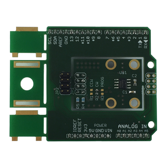
AMS AS5600 Manuale operativo - Pagina 5
Sfoglia online o scarica il pdf Manuale operativo per Unità di controllo AMS AS5600. AMS AS5600 10. 12-bit programmable contactless potentiometer
Anche per AMS AS5600: Manuale operativo (12 pagine), Manuale (14 pagine), Manuale d'uso (13 pagine)

AS5600-SO_EK_AB
Operation Manual
2.3 Mechanical Setup
To set up a contactless potentiometer a magnet holder and a magnet are needed to be used with
the AS5600 position sensor on a PCB. The configuration is shown in
Figure 2:
Mechanical Configuration
The magnet should be aligned by reading the output of the AGC register of the AS5600. For optimal
alignment, the AGC value is in the middle of the AGC range.
Note: If the magnetic field seen by the AS5600 is below 8mT, the output is switched off and
permanent angle programming is not possible.
2.4 Electrical Setup
The adapterboard is many used in following configurations in 5V or in 3.3V mode.:
2.4.1 3-Wire Mode
In this mode, the power supply and the output pin of the adapterboard are connected. To program a
custom angular output range, short R3 using a 0R resistor to enable the programming option B.
Follow the step-by-step instructions in the AS5600 datasheet to program the device.
Figure 3:
Using the board in 3-Wire Mode
Analog or PWM IN
www.ams.com
Arrow.com.
Arrow.com.
Arrow.com.
Arrow.com.
Arrow.com.
Downloaded from
Downloaded from
Downloaded from
Downloaded from
Downloaded from
+
-
µC
Revision 1.0 / 05.05.2014
Figure
2.
Magnet Holder (non-magnetic)
Sensor Magnet (d6x2,5)
AS5600
PCB
page 5/10
