Atkinson Electronics GSCM-mini-P Manuale - Pagina 13
Sfoglia online o scarica il pdf Manuale per Unità di controllo Atkinson Electronics GSCM-mini-P. Atkinson Electronics GSCM-mini-P 18. Generator start control module
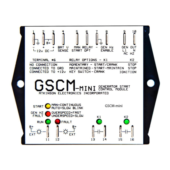
GSCM-mini-P
Wires to the Remote/ATS connector
The GSCM-mini-P uses the generator's Remote/ATS connector for all connections to the generator. The GSCM-mini-P's
power, relay and run feedback connections us the ATS connector as shown above. A control C1 relay is wired in series with
the ground wire to break the ground connection running to the engine switch terminal #5. The C1 relay connects as follows
terminals 86 and 30 connect to ground, terminal 85 connects to engine switch terminal #1 and terminal 87a connects to
engine switch #5. Engine switch to be left in the OFF position.
The GSCM-mini-P's terminal #6 is connected to terminal #3 (+12vdc) and to Samlexs's normally open relay contact, and the
common contact wires back to terminal #5 on the GSCM-mini-P. The generators DC output is wired to terminals # 7 & 8
providing the run feedback signal. An optional Battery tender/charger is not needed for this option.
The GSCM-mini-P accepts Samlex's two wire relay contact (maintained run signal) and provides a one second start /stop pulse
as outlined on page 6 GSCM-mini-P opion#2.
If a battery tender/charger is used, the engine switch should be left in the ON position and the C1 control relay is not used.
www.atkinsonelectronics.com
Circuit Board Division
800.261.3602
Cummins/Onan P9500DF generator & Samlex Inverter
13
Revised 02/21