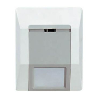
ADEMCO 4275EX-SN Istruzioni per l'installazione - Pagina 2
Sfoglia online o scarica il pdf Istruzioni per l'installazione per Sensori di sicurezza ADEMCO 4275EX-SN. ADEMCO 4275EX-SN 2. Passive infrared motion detector

TO THE INSTALLER
Regular maintenance and inspection (at least annually) by the
installer and frequent testing by the user are vital to continuous
satisfactory operation of any alarm system.
The installer should assume the responsibility of developing and
offering a regular maintenance program to the user, as well as
acquainting the user with the proper operation and limitations of
the alarm system and its component parts. Recommendations
must be included for a specific program of frequent testing (at
least weekly) to ensure the system's operation at all times.
WARNING
THE LIMITATIONS OF YOUR PASSlVE
INFRARED MOTION DETECTOR
While the Intrusion Detector is a highly reliable intrusion
detection device, it does not offer guaranteed protection against
burglary. Any Intrusion Detection device is subject to
compromise or failure to warn for a variety of reasons:
•
Infrared Motion Detectors can detect intrusion only within the
designed ranges as diagrammed in this installation manual.
•
Passive Infrared Motion Detectors do not provide volumetric
area protection. They do create multiple beams of protection,
and intrusion can be detected only in unobstructed areas
covered by those beams.
•
Passive Infrared Detectors cannot detect motion or intrusion
that takes place behind walls, ceilings, floors, closed doors,
glass partitions, glass doors, or windows.
•
Mechanical tampering, masking, painting or spraying of any
material on the mirrors, windows or any part of the optical
system can reduce the detection ability of the Passive
Infrared Motion Detector.
•
Passive Infrared Detectors sense changes in temperature;
however, as the ambient temperature of the protected area
approaches the temperature range of 32° to 40°C, the
detection performance can decrease.
•
This Passive Infrared Detector will not operate without
appropriate DC power connected to it or if the DC power is
improperly connected (i.e. reversed polarity connections).
•
Passive Infrared Detectors, like other electrical devices, are
subject to component failure. Even though they are designed
to last as long as 10 years, the electronic components could
fail at any time.
We have cited some of the most common reasons that a Passive
Infrared Motion Detector can fail to catch intrusion. However, this
does not imply that these are the only reasons, and therefore, it
is recommended that weekly testing of this type of unit, in
conjunction with weekly testing of the entire alarm system, be
performed to ensure that the detectors are working properly.
Installing an alarm system may make the owner eligible for a
lower insurance rate, but an alarm system is not a substitute for
insurance. Homeowners, property owners and renters should
continue to act prudently in protecting themselves and continue
to insure their lives and property.
We continue to develop new and improved protection devices.
Users of alarm systems owe it to themselves and their loved
ones to learn about these developments.
a. TOP VIEW
b. SIDE VIEW
35'
a.
10.5m
12'
3.6m
a. TOP VIEW
12'
3.6m
b. SIDE VIEW
35'
10.5m
ÊN2986-2U
N2986-2 8/99
1) INSERT SCREW-
DRIVER BLADE
HERE AND TWIST
MIRROR
REST
MOUNTING SURFACE
WIRE ENTRY AREA SEE
DETAIL "A"
SLOTS (4)
ENGAGE SLOTS ONTO
HOOKS AND SLIDE
HOUSING BASE
DOWN FIRMLY.
(PUNCTURE LABEL
ON BASE BEFORE
HOOKS (4)
INSTALLING)
EARS (4) FOR
CORNER MOUNTING
(MAY BE BROKEN
OFF IF MOUNTED ON
FLAT WALL)
WALL PLATE
INTERLOCKING TAB ENTERS CUTOUT
IN BASELOCKS BASE TO PLATE.
a.
12'
3.6m
12'
3.6m
b.
7'
2.1m
0
3'
10'
35'
1m
3m
10.5m
a.
10.5m
12'
3.6m
12'
3.6m
b.
7'
2.1m
0
3'
10'
35'
1m
3m
10.5m
DEAD ZONE
(APPROX)
®
ALARM DEVICE MANUFACTURING CO.
A DIVISION OF PITTWAY CORPORATION
165 Eileen Way, Syosset, New York 11791
Copyright © 1999 PITTWAY CORPORATION
2)
LIFT
COVER
Diagram 1
TERMINAL
BLOCK
PC BOARD
MIRROR PLASTIC PRONGS
(HOLD MIRROR
IN PLACE)
Diagram 2
BASE'S THIN WALL
IN WIRE ENTRY AREA
CAN BE CUT OR
BROKEN AWAY FOR
SURFACE WIRING.
HOUSING BASE
(COVER REMOVED)
Diagram 3
a.
10'
3m
0
10'
3m
15'
4.5m
6'
1.8m
b.
0
35'
35'
10.5m
b.
7'
2.1m
0
3'
10'
35'
1m
3m
10.5m
0
CEILING
10'
CEILING
12'
HEIGHT
(3m)
(3.6m)
FLOOR
FLOOR
0
Diagram 4. DETECTION AREA
Ceiling Mounted Unit Using Long Range ("Curtain") Mirror
TOP EDGE
OF
WALL PLATE.
C L
HOLE (3) FOR MOUNTING
THE PLATE TO WALL
Detail "A"
LED
POLLING
LOOP
+
–
PULSE COUNT SW #1 ON,
WALK-TEST SW #2 DISABLED
INSTANT
WALK TEST
NOTE: ID switches 1 thru 2 are set to
"ON" when placed in the right position.
Diagram 5
15'
4.5m
12'
35'
a.
3.6m
10.5m
12'
3.6m
b.
7'
2.1m
0
3'
10'
35'
1m
3m
10.5m
TOP
4'
VIEW
(1.2m)
[at 12 ft.
(3.6m)
ceiling
height]
18'
(5.5m)
Mount unit so that
PIR window is towards
detection area.
SIDE
VIEW
10'
15'
20'
(3m)
(4.6m)
(6m)
5 /16 (8mm) DIAMETER
(MAX) WIRING CIRCLE
IN MOUNTING SURFACE.
TOP OF HOLE MUST BE
ON LINE WITH TOP EDGE
OF WALL PLATE.
DETAIL
"A"
= ON
= OFF
DIP
SWITCH
PULSE COUNT
W/T DISABLED/ALARM
