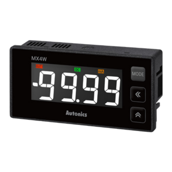
Autonics MX4W Series Manuale del prodotto - Pagina 5
Sfoglia online o scarica il pdf Manuale del prodotto per Strumenti di misura Autonics MX4W Series. Autonics MX4W Series 6. Lcd multi panel meters

Output Operation Mode
• The below describes based on OUT1.
• OUT1 and OUT2 of output operations are same. It operates individually by the set output
operation mode.
• When changing output operation mode, high-limit / low-limit output setting value, hysteresis
are reset.
MODE
Output operation
OFF
OUT
OUT.H
HIGH
OUT
OUT.L
LOW
OUT
OUT.H
OUT.L
HL
OUT
OUT.H
OUT.L
HL-G
OUT
Reset
01. Press the [◀] + [▲] + [▼] keys for over 5 sec. in run mode, INIT and NO flash
alternately for 0.5 sec in turn.
02. Change the setting value as YES by pressing the direction keys.
03. Press the [MODE] key to reset all parameter values as default and to return
to run mode.
Error
Error display is released automatically when it is in the measured and display range.
Display
Description
Flashes when measurement input is exceeded the
max. allowable input (110 %)
HHHH
Flashes when measurement input is exceeded the
min. allowable input (-DC: -110 % / DC, AC: -10 %)
LLLL
Flashes when measurement input is exceed the
max. display value (9999)
D-HH
Flashes when measurement input is exceed the
min. display value (-9999)
D-LL
Flashes when input frequency is exceeded the
max. display value of measured range
F-HH
Flashes when power factor display value to
measured input is over than LAG 0.50
PF-H
Flashes when power factor display value to
measured input is less than LEAD -0.50
PF-L
Flashes twice when it exceeds zero range (±99)
and returns to run mode
OVER
Preset output
ON
OFF
No output
Hys
OU1.H
OU1.H - HYS.1 ≥
≤ Display value
Display value
OU1.L
OU1.L + HYS.1 ≤
Hys
≥ Display value
Display value
OU1.L
OU1.L + HYS.1
Hys
≥ Display value
≤ Display value
/
/
OU1.H
OU1.H - HYS.1
≤ Display value
≥ Display value
OU1.L - HYS.1
OU1.L
≥ Display value
Hys
≤ Display value
/
≤ OU1.H + HYS.1
OU1.H + HYS.1
≤ Display value
Troubleshooting
Disconnect power supply
and check the cables.
Reset within the display
range.
-
Reset within the zero range.
Power Factor Display
• Power factor display is only available for DC input specifications.
• This function displays LEAD and LAG by analog output signal from the power factor
transducer.
- LEAD: current phase leads voltage phase
- LAG: current phase lags behind voltage phase
• It is available to accept several outputs of the power factor transducer by high / low-
limit input value analog output value setting in the power factor transducer.
• Power factor value is displayed as cosØ value -0.50 (LEAD) to 1.00 to 0.50 (LAG).
• Setting range: from min. to max. selected value from input range
• E.g.: When setting 200V in input range, high / low-limit input value are available to set from
-200.0 to 200.0. When setting 20V, high / low-limit input value are available to set from
-20.00 to 20.00.
(high-limit input value > low-limit input value)
Display
value
cosØ
LEAD
LAG
1
0.5
(H-RG)+(L-RG)
L-RG
H-RG
2
• E.g. 1: When the output of the power factor transducer is DC 4 - 20 mA
1. Connect the output to the input terminal 7 (+), 8 (-) of this unit, then set input range as 4-20.
2. When setting the input range as 4-20, low-limit input value is set as 4.00 and high-limit input
value is set as 20.00 automatically.
3. If measured input is 4 mA, it displays -0.50. For 12 mA measured input, it displays 1.00 and for
20 mA, it displays 0.50.
• E.g. 2: When the output of the power factor transducer is 1 - 5 VDCᜡ
1. Connect the output to the input terminal 6 (+), 8 (-) of this unit, then set the input range as
1-5B.
2. Set high-limit input value as 5.00 and low-limit input value as 1.00 for the output of the
power factor transducer.
3. If measured input is 1 V, it displays -0.50. For 3 V measured input, it displays 1.00 and for 5
V, it displays 0.50.
High-limit input value
0.50
0.75
0.90
1.00
-0.90
-0.75
-0.50
Low-limit input value
1V
1
0.9
0.5
LEAD
• E.g. 3: When LEAD value is smaller than -0.90, LAG value is smaller than 0.90, and OUT1 is used
1. Set OUT1 output operation mode as HL at parameter 2 group.
2. Set OUT1 high-limit output setting value as 0.90 and OUT1 low-limit output setting value as
-0.90 at parameter 0 group.
3. OUT2 output operation mode is also same setting as OUT1 output operation mode.
Output mode
HL
OUT1 high-limit
LAG
0.90
output setting value
1.00
OUT1 low-limit
-0.90
LEAD
output setting value
Default
H-RG
MX4W-V
500.0
MX4W-A
5.000
Input
value
3V
5V
LAG
Input value
Hys
Hys
Output value
L-RG
000.0
0.000
