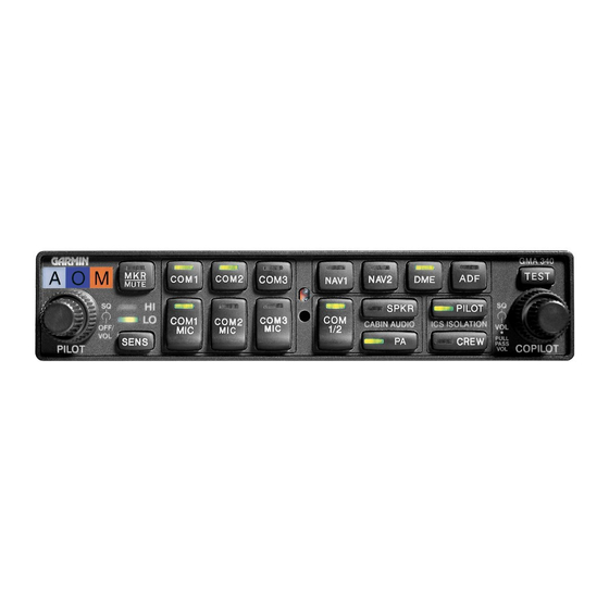
Garmin GMA 340 Manuale di installazione - Pagina 13
Sfoglia online o scarica il pdf Manuale di installazione per Display avionico Garmin GMA 340. Garmin GMA 340 43. Audio panel
Anche per Garmin GMA 340: Manuale del pilota (12 pagine), Manuale operativo supplementare (10 pagine), Manuale del pilota (4 pagine), Manuale del pilota (8 pagine), Manuale del pilota (8 pagine), Manuale del pilota (12 pagine)

2.1
INTRODUCTION
This section provides the necessary information for the installation and checkout of the GMA 340 Audio Panel.
Installation of the GMA 340 will differ according to equipment location and other factors. Cabling will be
fabricated by the installing agency to fit these various requirements. Appendix B contains interconnect wiring
diagrams, mounting dimensions, and information pertaining to installation. Each installation shall be
accomplished to meet the requirements of FAA AC 43.13-2A.
2.2
UNPACKING AND INSPECTING EQUIPMENT
Carefully unpack the equipment and make a visual inspection of the unit for evidence of damage incurred during
shipment. If the unit is damaged, notify the carrier and file a claim. To justify a claim, save the original shipping
container and all packing materials. Do not return the unit to Garmin until the carrier has authorized the claim.
Retain the original shipping containers for storage. If the original containers are not available, a separate
cardboard container should be prepared that is large enough to accommodate sufficient packing material to
prevent movement.
2.3
ANTENNA INSTALLATION
2.3.1
Location Considerations
The marker beacon antenna should be mounted on a flat surface on the underside of the aircraft. Mount the
antenna so that there is a minimum of structure between it and the ground radio stations. Locate as far away as
possible from transmitter antennas.
Best results with split COM mode will be obtained when the COM 1 and COM 2 antennas are mounted on
opposite sides of the aircraft (top/bottom).
2.3.2
Antenna Installation
Install the antenna according to the antenna manufacturer's instructions and FAA AC 43.13-2A.
2.3.3
Antenna Cable Installation
Use coax meeting the applicable aviation regulation for the marker beacon antenna cable. When routing the
cable, avoid sharp corners and route away from high current wiring, fluorescent lighting, and any transmitter
antenna cables. Follow accepted industry practices when installing the BNC connector at the antenna end of the
cable. Use a BNC connector suitable for the type of cable used.
GMA 340 Installation Manual
190-00149-01
SECTION 2
INSTALLATION
Page 2-1
Rev. L
