A-M Systems 1700 Manuale - Pagina 6
Sfoglia online o scarica il pdf Manuale per Amplificatore A-M Systems 1700. A-M Systems 1700 16. Four-channel differential ac amplifier

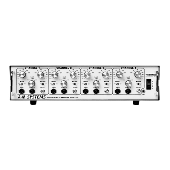
Controls and Connectors
This 5-pin connector attaches the electrode cable
INPUT:
to the amplifier channel. The pin and electrode cable
wire designations can be found in the "Operating
Instructions" section in this manual.
This 5-pin connector allows for external
STIMULUS:
signals to be applied to the electrode.
MODE (STIM-REC):
Stimulus Mode or Record Mode. In Stimulus Mode,
the
connector is connected to the signal from the
INPUT
connector is disabled. In Record Mode, the
OUTPUT
the amplification circuits and the signal is available at the
This rotary switch sets the amplifier gain to x100, x1000, or x10 000.
GAIN:
This rotary switch selects the cut-off frequency of the Low Frequency
LOW CUT-OFF:
Filter for the amplifier channel. Signals below the cut-off frequency are reduced by a
factor of 100 (40 dB) per decade decrease in the input signal frequency. The Low
Frequency Filter may be used to reduce slow DC level variations in the signal being
recorded (See Bode plot page 3).
This rotary switch selects the cut-off frequency of the High Frequency
HIGH CUT-OFF:
Filter for the amplifier channel. Signals above the cut-off frequency are reduced by a
factor of 100 (40dB) per decade increase in the input signal frequency.
This switch allows the Notch Filter to be included (
NOTCH (IN-OUT):
(
) from the signal processing circuitry on a per channel basis. When radiation from
OUT
the power lines is present, it is picked up by recording electrodes creating unwanted
interference in the recording signal. This interference can be reduced through proper
grounding and shielding techniques. Occasionally it is impossible to reduce this
interference sufficiently to record relatively noise-free signals. The Notch Filter can
sufficiently reduce the interference. However, this filter causes some distortion in
signals below 100 Hz.
This BNC connector provides the output signal from the amplifier channel.
OUTPUT:
This switch turns on power to all four amplifier channels.
POWER:
This connector is attached to the circuit ground for all four amplifier channels. To
GND:
obtain low-noise recordings, this terminal may be used to make a ground connection
to the recording medium.
A-M Systems
This switch sets the channel to
131 Business Park Loop, P.O. Box 850 Carlsborg, WA 98324
Telephone: 800-426-1306 * 360-683-8300 * FAX: 360-683-3525
E-mail: [email protected] * Website:
connector and the
STIMULUS
connector is connected to
INPUT
connector.
OUTPUT
) in or excluded
IN
http://www.a-msystems.com
2
