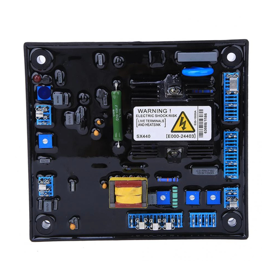
AVR SX440 Manuale operativo - Pagina 4
Sfoglia online o scarica il pdf Manuale operativo per Controllore AVR SX440. AVR SX440 4. Generator automatic voltage regulator

UFRO
STAB
LED
Figure 1 Outline Drawing
SX440
Figure 2 Bypass Drawing
6. TROUBLE SHOOTING
SYMPTOM
Engine speed is too low
Voltage does not
build up
wires are not connected well
Defective Generator
External VR broken
Out voltage low
Terminal 1&2 not linked
Terminal 3&2 no sensing input
Under frequency
Defective Generator
AVR adjustment not well
Out voltage high
Defective Generator
※ Use only original supplied spare protection fuse for fuse replacement.
※ Please accept our sincere apology if any modification in performance, specification or appearance is
made without prior notice.
______________________________________________________________________________________
4
All manuals and user guides at all-guides.com
TRIM
DROOP
VOLT
C-A < 90KW
C-B 90-550KW
B-A > 550KW
C B A
UNITS : mm
CAUSE
ATTENTION
1. AVR can be mounted directly on the
engine, genset, switchgear, control
panel, or any position that will not
affects operation. For dimension
reference, please see Figure 1.
2. All voltage readings are to be taken
with an average-reading voltmeter
Meggers and high-potential test
equipment must not be used. Use of
such equipment could damage the
AVR.
Figure 3 Wiring Drawing
CORRECTION
Please refer to the Generator Manual
Please refer to Figure 2
Please refer to the Generator Manual
Check wiring and testing VR
Please linked terminal 1&2
Please refer to Figure 2
Please refer to the Generator Manual
Please refer to the Generator Manual
Please refer to voltage adjustment page
Please refer to the Generator Manual
SX440
