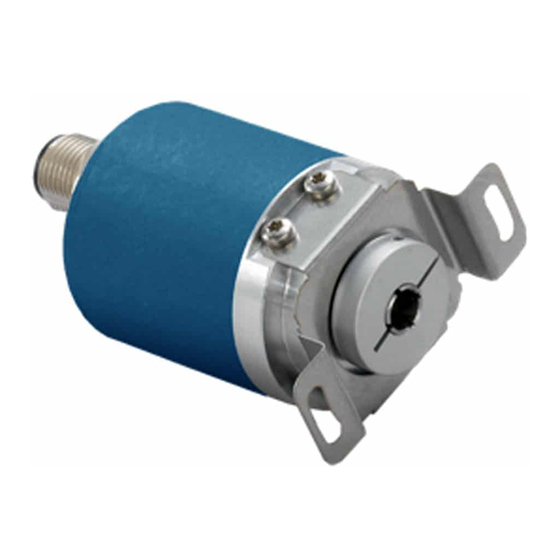
Avtron HS6M Manuale di istruzioni - Pagina 9
Sfoglia online o scarica il pdf Manuale di istruzioni per Convertitore multimediale Avtron HS6M. Avtron HS6M 16. Hollow shaft 6-15mm

Profibus DP Protocol "P"
Profibus DP is typically a master-slave network-the master/scanner
device gathers data from each (slave) device on the bus. Avtron
encoders are Profibus DP slave devices.
Profibus may be wired in several different configurations, but the
most common is a "Daisy-Chain" configuration. The master/scanner
device may be located at any point along the bus. The cable must
be terminated at each end with 150 ohm resistors. Note that
Profibus DP also offers the option to carry device power to each
encoder through an additional cable pair of wires.
Preferred cable: Nidec Avtron recommends structured Profibus DP
wiring systems, available from a broad range of vendors.
For more details on Profibus, consult the Profibus Users Association
(PI):
http://www.profibus.com/
Number
of
2
16
Nodes
Max.
Overall
750
690
640
Cable
[229]
[210]
[190]
Length*
Network
12M
1.5M
Baud
6M
Rate
3M
Max.
325
650
Length*
[100]
[200]
*Using Profibus standard cable, 150 ohm impedance 3-20mHz,
<30pf/m, <110 ohms/km loop resistance
Setting Station/Node, Baud Rate & Termination Resistor
To set the node number: use the rotating switches in the connection
cap. The format is decimal, from 0-99 (ten's switch and one's
switch). Software/master address changes are not supported.
NOTE: Each device must have a unique node address, and this
address must be different than the master/scanner module.
Profibus DP baud rate is auto-detected by the encoder, no settings
are required. 12 MBaud, 6 MBaud, 3 MBaud, 1.5 MBaud, 500 kBaud,
187.5 kBaud, 93.75 kBaud, 45.45 kBaud, 19.2 kBaud, 9.6 kBaud are
all supported.
To enable the termination resistor: Move the switch "R" to the "On"
Position on the connection board. The termination resistor should
be turned on/enabled when the encoder is the last/only device on
the bus. Note that standard 9 pin DIN connectors used for Profibus
DP also offer a termination resistor. Be sure NOT to enable both the
encoder termination resistor and the 9-pin connector resistor, use
one or the other for an encoder at the end of a bus.
Measuring Position, Speed, and Acceleration
To read position and speed feedback into your device (Acceleration
measurement is not supported.): Following the instructions for
your master/scanner module for the Profibus DP network, load the
encoder GSD file into your configuration. Assign it to the correct
node number. Store the configuration to the scanner module.
All of the position data and other parameters will be read by
the scanner module and placed in registers identified in the
configuration package.
For multiturn & single turn encoders: position data provided as
4 bytes, 32 bits: Format is little-endian (lowest bit = right-most
bit). Single-turn data/data within 1 turn is provided in the least-
32
64
Units
560
ft
[170]
[m]
500K 187.5K 93.75K
Units
45.45K
19.2K
9.6K
1300
3250
4000
ft
[400]
[1000]
[1200]
[m]
significant bits. Multiturn data is provided directly "above" the
single turn data, bitwise. Example: 12 turns x 13 bits/turn encoder,
lowest 13 bits = position within one turn, next 12 bits (up to bit 25)
represent turns position data.
Setting Zero Position for Multiturn Encoders and Single turn
Encoders Using 32 Bit Feedback:
Write 1 to the highest bit (31)-write 128 (80H) to top-most-byte of
the position register.
For single turn encoders: position data can instead be provided as 2
bytes, 16 bits: Format is little-endian (lowest bit = right-most bit).
Setting Zero Position for Single turn Encoders Using 16 Bit
Feedback :
Write 1 to the highest bit (15)-write 128 (80H) to top-most-byte of
the position register.
Isochronous (Auto-Transmit) Mode
DPV2 Isochronous communication can be configured using the
optional DPV2 GSD file. Load the encoder GSD file into your master/
scanner software. Assign it to the correct node number. Store the
resulting configuration into the scanner module. Note many Profibus
master devices do not support isochronous mode-check the master
device manual before utilizing this encoder mode.
Other Parameters
Contact Nidec Avtron for additional parameters, diagnostic registers,
cam and programmable limit switch functionality and other
advanced features.
HS6M
9
