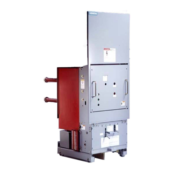
Siemens 15-FSV-750 Installazione Funzionamento e manutenzione - Pagina 20
Sfoglia online o scarica il pdf Installazione Funzionamento e manutenzione per Interruttore Siemens 15-FSV-750. Siemens 15-FSV-750 48. Vacuum circuit breakers fsv series and msv series

Interrupter/Operator
Description
50 1
Open1ng for handcrank
50 2
Charging mechanism
50 3
Charg1ng flange
50 3 1
Driver
50 4
Motor
53
Close button
53 1
Spring Release Coil
55 1
L 1 nkage
Control lever
55 2
6 2
Clos1ng spring
62 1
Charg1ng shaft
Crank
6 2 . 2
62 3
Cam
Lever
6 2 5
62 5 1
Pawl roller
Latching Pawl
6 2 5 2
Dnve lever
6 2 6
62 8
Trip free Coupl1ng rod
Figure 10
Operating Mechanism, Details of Closing Spring Charging Components
Construction
The essential parts of the operating mechanism are shown in
Fig. 9. Its actuation is descri bed u nder "Operator Sequential
Operation Diag ram" on page 17.
Indirect Releases (Tripping Coils)
The shunt releases convert the electrical tripping pulse into
mechanical energy, it's function being to release the tripping
spring . The undervoltage release may be manually actuated
by a make or a break contact. In the make contact case, its
coil is shorted out, built-in series resistors l i miting the cu rrent.
Motor Operating Mechanism
The spring charging motor (50 9) is bolted to the charging
mechanism (50.2) gear box installed in the mechanism hous
ing. Neither the charg ing mechanism nor the motor require
any serving.
Auxiliary Switch
The auxiliary switch is actuated by the breaker shaft.
Mode of Operation
The operating mechanism is of the stored-energy trip free type,
i . e . the charging of the s pring is not automatically followed by
the contacts changing position, and the closing function may
be overridden by a trip command at any time.
55 2
6 2 1
62 2
55 1
6 2
50 2
50 3
50 3 1 62 3
62 5
50 1 50 4
6 2 . 8
6 2 6
When the stored-energy mechanism has been charge
instant of operation can be chosen as desired .
The mechanical energy for carrying out an "open-close-open "
sequence for auto-reclosing d uty is stored in the closing and
tripping s p rings.
Charging
The details of the closing spring charging mechanism are shown
in figures 9, 10, 11 and 12. The charging shaft, (62.1 ) , is sup
ported in the charging mechanism, (50.2), but is not coupled
mechanically with the charging mechanism. Fitted to it are the
crank, (62.2), at one end and the cam , (62.3), together with
lever, (62.5), at the other.
When the charg ing mechanism is actuated by hand with a
hand crank opening or by a motor, the flange, (50.4), the flange.
50.3, turns until the d river, (50.3.1 ) , locates in the cutaway part
of cam disc, (62 3), thus causing the charging shaft to follow.
The crank, (62.2), charges the closing s p ring (62). When this
has been fully charged the crank actuates the linkage, (55.1 ) ,
via control lever, (55.2), for the "closing s p ring charged" indi
cator, (55), and actuates the limit switches, (50.4.1 ), for inter
ru pting the motor supply. At the same time, the lever (62.5) at
the other end of the charging shaft i s securely locked by the
latching pawl (62. 5.2). When the closing spring is being
charged, cam disc, (62.3), follows idly, i.e. it i s brought into
position for closing .
Page 15
62 5 2
62 5 1
1
53
5 3
�
. the
