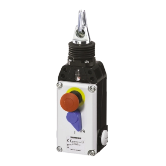
Siemens SIRIUS 3SE7141-1EG10 Manuale di istruzioni per l'uso - Pagina 2
Sfoglia online o scarica il pdf Manuale di istruzioni per l'uso per Interruttore Siemens SIRIUS 3SE7141-1EG10. Siemens SIRIUS 3SE7141-1EG10 10. Emergency cable-operated switch with integrated emergency stop

SIRIUS
Emergency cable-operated switch with integrated EMERGENCY STOP
Operating Instructions
Read and understand these instructions before installing, operating, or main-
taining the equipment.
DANGER
!
Hazardous voltage.
Will cause death or serious injury.
Disconnect power before working on equipment.
Reliable functioning of the equipment is only ensured with certified components.
Important notice
The products described herein are designed to be components of a customized
machinery safety-oriented control system. A complete safety-oriented system
may include safety sensors, evaluators, actuators and signaling components. It
is the responsibility of each company to conduct its own evaluation of the effec-
tiveness of the safety system by trained individuals. Siemens AG, its subsidia-
ries and affiliates (collectively "Siemens") are not in a position to evaluate all of
the characteristics of a given machine or product not designed by Siemens.
Siemens accepts no liability for any recommendation that may be implied or sta-
ted herein. The warranty contained in the contract of sale by Siemens is the sole
warranty of Siemens. Any statements contained herein do not create new war-
ranties or modify existing ones.
Application
Safety cable-operated switches are used in those positions where an EMER-
GENCY STOP command must be accessible from all points of a machine, sys-
tem or plant. An EMERGENCY STOP command is applied by pulling the pre-
stressed pull-cable or by pressing the EMERGENCY STOP button (push but-
ton).
Design/Operating principle
The 3SE7 141-1 EG 10 wire switches have 3 NC contacts and 1 NO contact.
With the pre-stressed wire rope the NC contacts (11-12 / 21-22 / 31-32) are
closed and the NO contact (43-44) is open. When the cable is pulled or the
EMERGENCY STOP button is pressed the NC contacts (e.g. 11-12 etc.) open,
the NC contact (e.g. 43-44) closes and all contacts are locked in their respective
states. The blue swivel lever is used to unlock the contacts.
Unlocking is only possible in the middle - pre-stressed - position.
Installation
During the installation (see figure II/III) the switch needs to be pre-stressed to
such an extent that the needle in the display window moves to the middle posi-
tion. The cable-operated switch must be installed in such a way that it can be
safely unlocked manually.
The red PVC sheathing must be removed from the wire rope in the terminal area
before the pull cable is attached. The wire rope must be installed in accordance
with the installation notes.
Since the thimbles deform when the cable is pulled the cable should be pulled
forcefully several times after installation. The cable then needs to be re-stressed
using a DUPLEX terminal, eyebolt or tightener.
Attention: Cable supports are necessary (after every 5 m) for cable lengths
greater than 10 m. With increasing cable lengths the ambient temperature range
is more and more restricted due to the thermal expansion of the cable (see
figure III/A).
Wiring and sealing
Adequate cable glands with the appropriate degree of protection must be used
for the cable entry. There are three M20X1.5 cable entries. The cover screws
must be loosened to open the cover.
After wiring it is essential to tidy up the inner part of the switch (e.g. all conduc-
tor cut-offs must be removed), since foreign objects can influence the switching
performance of the switch. After the wiring process has been completed, the
cover must be reattached by uniformly tightening the cover screws.
2
Order No.: 3ZX1012-0SE71-2AA1
Notice
The switch must only be operated by pulling the pull cable and not by levering
out the mechanical system or by pulling out the pulling device using tools.
The operator must convince himself/herself regularly of the safe functioning of
the EMRGENCY STOP device.
Technical data
Standards applied
IEC 60947-5-5 / EN 60947-5-5
Enclosure
GD-AL alloy, painted
Cover
Impact-resistant thermoplast
Degree of protection
IP67 acc. to IEC 60529 / EN 60529
Switching system
...-1 EG 10 = 3 NC contacts and 1 NO contact
Type of connection
Connection terminal for 2.5 mm
0.05 mm
Cable entry
3SE7 141-...= 3 x M20x1.5
Cable length
3SE7 141-... max. 75 m
(observe ambient temperature range)
Mech. service life
> 10
Permiss. operating temperature–25 °C .up to +70°C (observe cable length)
Permiss. electr. load
250 V AC AC15: 2 A / 250 V
Short-circuit strength
6 A gL/gG D fuse
.
Characteristics / Specifications
– Complies with EN 418 / IEC 60947-5-5
– 4 contacts
– Integrated EMERGENCY-STOP button (see figure I/A)
– Cable tension and cable-break monitoring
– Twisting of the cable eye not possible
– Cable length 75 m
– Position displayed via display window (see figure I/B)
– Unlocking lever and display of the switching state (see figure I/C)
– Outside sealing sleeve (see figure I/D)
Wiring diagram
On
Off
3 NC / 1 NO
Cable break
Inspection
window
11
12
21
22
31
32
43
44
3SE7141-1EG10
English
acc. to IEC 60947-5-5
2
max. und
2
min.
6
switching cycles
DC13: 0.25 A / 230 V
Pull cable
Pull cable
Locking
Middle position
Locking
Cable break
Cable break
Middle position
Pull cable
Needle
11
12
11
21
22
21
31
32
31
43
44
43
12
22
32
44
