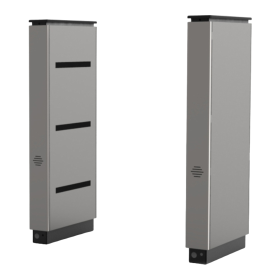
Alvarado Supervisor 500 Manuale di istruzioni per l'installazione - Pagina 10
Sfoglia online o scarica il pdf Manuale di istruzioni per l'installazione per Tornelli Alvarado Supervisor 500. Alvarado Supervisor 500 19. Barrier-free optical counting turnstile

Count Output Relays (Optional)
NOTE
This section is only applicable to SU500s being used in conjection with the optional GWCB-12 count controller. Output relays
are utilized to communicate count data to the GWCB-12. Verfiy that you have output relays installed as shown in [Figure 19].
1.
Locate the entry and exit output relays [Figure 19].
2.
Using a precision flat-blade screwdriver, wire the
relay's normally open (N.O) and common (COM)
terminals to the GWCB-12 input terminals
[Figure 19A].
NOTES
Relay wire shall be provided by the technician.
Refer to the GWCB-12 Installation & Maintenance Guide
(PUD3089) for wiring instructions.
Page 18
For Assistance: [email protected] +1 (909) 591-8431
SU500 Installation Instructions
Figure 19
Output Relays
Entry Relay
Exit Relay
Figure 19A
Output Relay Terminals
N.O.
COM
N.O.
COM
PUD1456R5-0
SU500 Installation Instructions
Ethernet Communication (Optional)
NOTE
It is assumed that Ethernet cabling has been run to the
turnstile via conduit and pulled through the conduit opening in
Step 6 of the Anchoring the Turnstile section.
1.
Locate the main turnstile controller in the master / center
cabinet.
2.
Connect the Ethernet cable to the Ethernet Port
[Figure 20].
Basic Operations
Powering On
The power is button located at the base of the master cabinet
on the secured side [Figure 21].
1.
Using a slim object such as a pencil or pen, push the
power button.
2.
The power-up cycle takes less than one minute to
complete. Two chimes sound during the power-up cycle
to indicate status:
•
Ascending Chime: Operating system booted
successfully.
•
Descending Chime: Turnstile application launched
successfully, and the power-up cycle is complete.
NOTE
After the boot-up cycle is complete, the SU500 enters
into the operating modes last configured.
PUD1R5-0
For Assistance: [email protected] +1 (909) 591-8431
Figure 20
Main Turnstile Controller
Ethernet
Port
Figure 21
Power Button
Power
Button
Page 19
