- ページ 5
インターホン・システム ASL INTERCOM PS 130のPDF ユーザーマニュアルをオンラインで閲覧またはダウンロードできます。ASL INTERCOM PS 130 11 ページ。 Pro series single channel remote speaker station
ASL INTERCOM PS 130 にも: ユーザーマニュアル (9 ページ), ユーザーマニュアル (13 ページ)
4.0
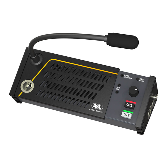
FRONT PANEL CONTROLS AND CONNECTOR
5.0
SIDE PANEL CONNECTORS
11 LINE connectors
These XLR-3 connectors are for connecting the PS
130 to the intercom system.
Pin assignments :
1. 0 V / ground shield
2. +30 V power wire
3. audio wire
The female connector is for input.
The male connector is for extending the intercom line
to other stations.
6.0
INTERNAL CONTROLS
Inside the unit there are two trimmers to adjust the mic
gain of the gooseneck microphone and the headset
microphone separately. These internal controls are located
on a P.C.board.
They can be reached as follows :
-
remove the screws of the bottom plate.
-
slide the plate to one side and take it out.
-
take away the plastic isolation plate.
User Manual PS 130 / Issue 1 © 1994 ASL Intercom, Utrecht, Holland.
The two trimmers are labeled :
GOOSE for the gooseneck microphone
HEADS for the headset microphone.
5