- ページ 5
インターホン・システム ASL INTERCOM PS 430のPDF ユーザーマニュアルをオンラインで閲覧またはダウンロードできます。ASL INTERCOM PS 430 9 ページ。 Pro series single channel remote speaker station
ASL INTERCOM PS 430 にも: クイックマニュアル (4 ページ), ユーザーマニュアル (14 ページ), ユーザーマニュアル (11 ページ)
The trimmer operating area is between fully
clockwise and minimum level. Adjusting the side
tones does not affect the level of your voice as it is
heard by other stations.
7
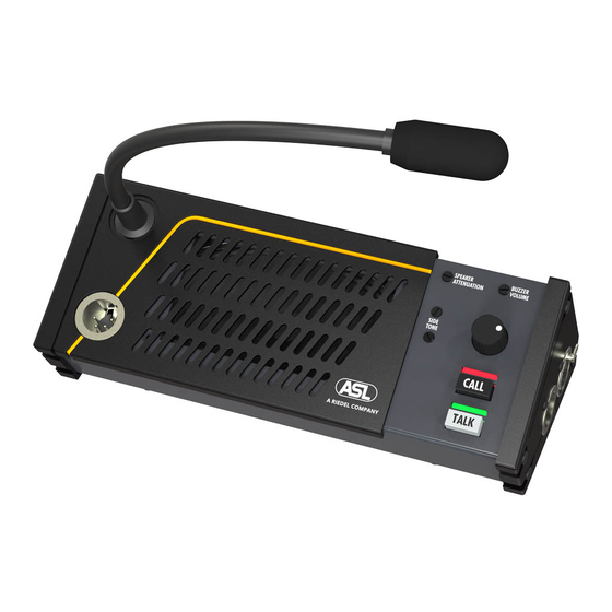
SPEAKER ATTENUATOR trimmer
This trimmer adjusts the extent to which the
loudspeaker is automatically dimmed when the
gooseneck microphone is switched on. It prevents
unit feedback if side tone rejection is not sufficient.
It also minimizes system feedback or a 'hollow'
sound when the gooseneck microphones of other
speaker stations (on one or several of the connected
party lines) are switched on as well.
Adjustment procedure :
o
make sure that there is no headset
connected
o
switch off all TALK buttons of the PS 430.
o
inject an audio signal on one of the intercom
channels via the aux input of a Pro Series
master station or separate power supply
o
turn up the listen volume of the PS 430
(channel – and master volume).
o
activate the gooseneck microphone (push
the TALK button of the selected channel)
o
adjust the desired degree of speaker
attenuation (turning the trimmer counter-
clockwise increases the attenuation)
8
BUZZER VOLUME trimmer
This trimmer adjusts the volume of the buzzer, which
is located behind the front panel.
6.0
SIDE PANEL CONNECTORS
12
LINE connector for channel A & B
13
LINE connector for channel C & D
These two XLR-5 connectors are for connecting the
PS 430 to the party lines of the intercom system.
One connector is for channels A and B, one
connector for channel C and D.
PAGE 5
User Manual PS 430 / Issue 2011 © ASL Intercom BV
.
The buzzer is activated when the CALL button of the
PS 430 (or a CALL button of any other station on the
party lines to which the PS 430 is connected) is
pushed for longer than 2 seconds, provided there is
no Buzzer Mute Signal on these party lines coming
from a Pro Series master station or separate power
supply.
9
HEADSET connector
This is an XLR-4 connector for the connection of a
local headset when private conversation is desired.
The headset must have a can impedance of
minimum 200 ohms. When the headset has two
cans in parallel, each can must have an impedance
of minimum 400 ohms. The headset microphone
may be of the dynamic or electret type
Pin assignments headset connector :
Pin 1.
Shield Mic. (GND)
Pin 2.
mic. +
Pin 3.
phones +
Pin 4.. phones -
When connecting a headset, loudspeaker and
gooseneck microphone are disabled automatically.
10
GOOSENECK microphone
This a noise canceling microphone. A limiter
prevents the mic pre-amp from clipping when
speaking close in the microphone. The gooseneck
mic. is automatically disabled when a headset is
connected to the PS 430.
11
LOUDSPEAKER
This is a high quality loudspeaker driven by a 2.9
Watt amplifier. The speaker is automatically disabled
when a headset is connected to the PS 430.
For linking the XLR-5 sockets to XLR-3 intercom
line connectors, each PS 430 comes with two
Y-cords, having an XLR-5 connector at one end and
two XLR-3 connectors at the other end.
On the Y-cords, the XLR-3 with the white ring
corresponds with channel A or C.
Pin assignment XLR-5 connector
1.
0 V / ground shield
2.
+30 V power wire channel
3.
audio wire channel
4.
+30 V audio wire channel
5.
audio wire channel
Pin assignment XLR-5 connector #13
1.
0 V / ground shield
2.
+30 V power wire channel
3.
audio wire channel
4.
+30 V audio wire channel
5.
audio wire channel
#12
A+B
A
A
B
B
C+D
C
C
D
D