- ページ 7
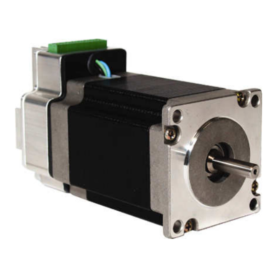
コントロールユニット AMCI SMD23-240のPDF ユーザーマニュアルをオンラインで閲覧またはダウンロードできます。AMCI SMD23-240 14 ページ。 Integrated stepper drive & motor

ADV ANC ED
MIC RO CON T RO L S INC.
INSTALLATION
The mounting flange functions as both a mounting mechanism and also a heatsink. Mount the SMD
to a thermally conductive surface that is as large as possible. Heat is conducted from the SMD to
the mounting fixture resulting in motor/drive cooling. For proper cooling, the SMD must be mounted
with the heatsink fins vertical. In extreme cases a cooling fan may be required.
SMD23 Outline Drawings
1.30"
±0.02"
(33.0 ±0.5)
AMCI Motor
SMD23-130
2.12" (53.8)
SMD23-240
2.98" (75.7)
REAR VIEW
20 Gear Drive, Plymouth Industrial Park, Terryville, CT 06786
Tel: (860) 585-1254
Fax: (860) 584-1973
Length
0.81"
±0.03"
(Length ±0.8)
(20.6 ±0.3)
0.06"
±0.01"
(1.5 ±0.3)
S
S
A
0.20"
±0.01"
0.59"
(5.1 ±0.3)
(15.0 ± 0.5)
Length
+ 0.0000"
∅ ∅ ∅ ∅ 0.2500"
– 0.0005"
(
∅ ∅ ∅ ∅ 6.350 + 0.000
– 0.013
Indexer Input Connector (8 Pins)
Mates with AMCI #: MS-8P
Phoenix Contact #: MC1,5/8-ST-3,81
Web: www.amci.com
SMD-23 Integrated Stepper Drive & Motor
±0.02"
0.001"
(0.03)
∅ 0.003"
A
(∅ 0.08)
1.72"
(43.7)
Max.
∅ ∅ ∅ ∅ 1.5000"
± 0.0010"
(∅ ∅ ∅ ∅ 38.100" ± 0.025)
+ 0.0000"
∅ ∅ ∅ ∅ 0.2500"
– 0.0005"
(
∅ ∅ ∅ ∅ 6.350 + 0.000
)
±0.02"
– 0.013
Section S – S (3X Scale)
)
0.228"
±0.004"
(5.79 ±0.10)
Pin 1 +Vdc
Pin 2 Vdc Common
Pin 3 – Disable
Pin 4 + Disable
–
–
+
V
V
D
IN
IN
IS
1 2 3 4 5 6 7 8
1.520"
(38.61 ± 0.13)
1.858"
±0.005"
(47.19 ±0.13)
2.20"
±0.02"
(55.9 ±0.5)
Pin 5 – Step
Pin 6 + Step
Pin 7 – Direction
Pin 8 + Direction
–
–
+
+
+
D
S
S
D
D
IS
TP
TP
IR
IR
0.43" Nominal
(10.9 Nominal)
±0.005"
+ 0.02"
4: ∅ ∅ ∅ ∅ 0.18"
– 0.00"
(
4: ∅ ∅ ∅ ∅ 4.6 + 0.5
)
– 0.0
page: 7
