- ページ 4
コントロールユニット AMS AS5601のPDF マニュアルをオンラインで閲覧またはダウンロードできます。AMS AS5601 13 ページ。 Usb interface & programming box
AMS AS5601 にも: 操作マニュアル (12 ページ), ユーザーマニュアル (13 ページ)

AS5601 Adapter Board
Header
Pin
Symbol
J2
2
B
J2
3
A
J2
4
PUSH
4
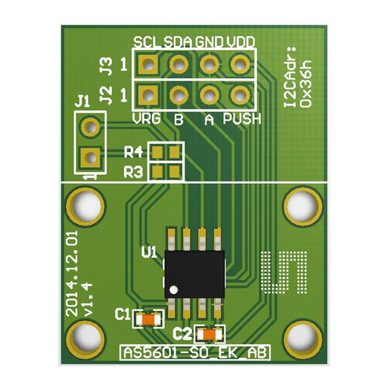
Adapter Board Description
The AS5601 is connected over the dual-row 2.54mm 4-pin header footprint. Connect the desired
pins of the AS5601 using the headers and resistors.
Figure 1:
Adapterboard Description
Short J1 to
operate in
3.3V mode
I2C pull-up
resistors
5
Mechanical Setup
To set up a contactless potentiometer a magnet holder and a magnet are needed to be used with
the AS5601 position sensor on a PCB. The configuration is shown in
ams Eval Kit Manual, Confidential
[v1-00] 2014-Jul-31
Description
Mode
Output Pin
Output Pin
Output Pin
Info
J1 in 3.3V Mode
Quadrature incremental signal B
Quadrature incremental signal A
Contactless pushbutton function output
Figure
2.
Page 4
Document Feedback
