- ページ 2
インターホン・システム ATIGO A501SのPDF インストレーション・マニュアルをオンラインで閲覧またはダウンロードできます。ATIGO A501S 5 ページ。 2 wire kit

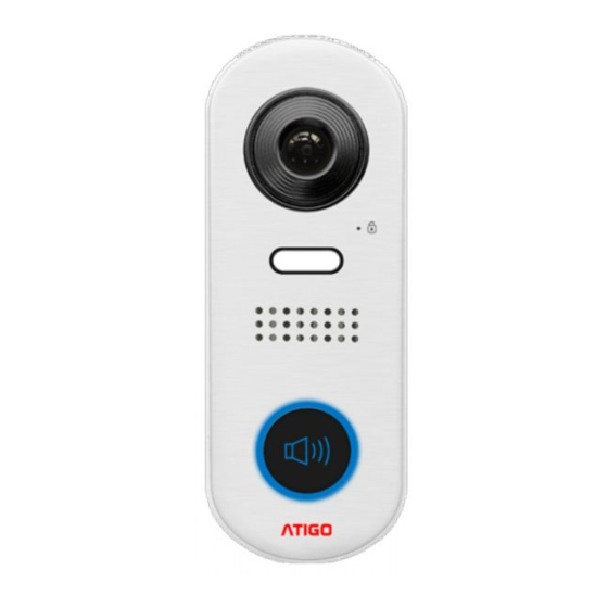
Door entry panel A501S
Connection Terminal
L1 and L2 is bus line connecting to terminal
BUS(DS) on the power supply
LK+ and LK- is a lock/relay output, set by the
jumper.
JP lock power mode (internal/external power)
Specification:
Power supply: 26Vdc (supplied by A2100)
Power consumption: 14mA standby,
Camera: Colour CMOS, 2 Mega pixels,
1/2.7" Fisheye, 155º Wide angle.
Unlock power output: 12Vdc, 250mA
Unlock time: 3, 5 or 10 seconds
Working temperature: -15ºC ~ +55ºC
Installation: Surface mounting
Dimension: 160(H) x 60(W) x 31.5(D)mm
DIP switch settings for A501S
The video door entry panel is configured by 6
DIP switches.
The DIP switches can be modified either
before or after installation. Restarting the unit
is necessary whenever the DIP switches have
been modified.
DIP switches 1 and 2 are for door station
default ID setting and must be set as 00.
DIP switches 3 and 4 are for setting door
unlock time.
DIP switch 5 is for setting lock type:
ON
Fail locked (normally closed)
OFF
Fail unlocked (normally open)
DIP switch 6 is for programming door entry
panel.
ON
Programming mode enabled
OFF
Programming mode disabled
122mA active
