- ページ 2
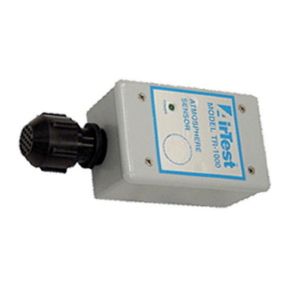
アクセサリー AirTest TR-1000のPDF 取扱説明書をオンラインで閲覧またはダウンロードできます。AirTest TR-1000 6 ページ。 4-20 ma sensor / transmitter, vehicle exhaust detection applications

4 – 20 mA SENSOR / TRANSMITTER MODEL TR-1000
INSTALLATION:
1.
Locate a flat surface to mount the enclosure so that the sensor can face
downward. If the rear power entry is to be used, remove the plug before
mounting the enclosure. The second power entry is at the end opposite
the sensor.
2.
Remove the cover of the enclosure by removing the 4 screws in the
corners. Be careful here since the circuit board is connected to the cover.
The circuit board is connected to the sensor, so the cover will hang from
these wires when removed. Remove the plug from the end power entry if it
is to be used.
3.
Connect the electrical fittings to the enclosure and bring in the electrical
wires. NOTE: BE SURE WIRING IS DONE ACCORDING TO THE LOCAL
ELECTRICAL CODE REQUIREMENTS. NOTE: To prevent shorting
problems do not leave ground wire to box bare (if one is used) – cover
with electrical tape.
4.
Connect the wires to the removable connector block as shown on the
wiring drawing. (See Fig.1)
CALIBRATION - SOLID STATE SENSORS:
The TR-1000 has been factory calibrated for a range of 0 – 400 ppm CO and is
ready for use. If however there is a level of background gases, it should be
calibrated on site. If the range is to be changed, the TR-1000 must be re-
calibrated.
1. Connect power and signal return wires to a suitable controller that will provide
sensor excitation and signal processing. (See Fig.1)
For all the following readings TP1 (RED) is the COMMON POSITIVE jack.
2. Power up the unit, the ready light will come on in 10 seconds. Check TP2
(Black) for correct voltage of 5.0V ±0.1V. If it is satisfactory let the sensor
burn-in for 24 hours. If voltage is unsatisfactory the board is faulty and must
be serviced.
3. TO SET ZERO
Adjust the ZERO potentiometer, RV1, until the ACTIVE LED (YELLOW) just
goes off.
INSTALLATION AND CALIBRATION
2
