- ページ 2
ネットワーク・ルーター 3onedata IES206G-2GS-PのPDF ユーザーマニュアルをオンラインで閲覧またはダウンロードできます。3onedata IES206G-2GS-P 4 ページ。 Industrial ethernet switch

range is 12 ~ 48VDC. The redundant power can be used
independently. PWR1 and PWR2 can supply power at the same
time, once either of these two powers fails, another power can
acts as backup automatically to ensure reliability of the network.
It also supports reverse polarity connection.
【Dimension】
Unit (mm)
【Communication connector】
10/100BaseT(X) Ethernet port
The pinout define of RJ45 port display as below, connect by UTP
or STP. The connect distance is no more than 100m. 100Mbps is
used 120Ωof UTP 5, 10Mbps is used 120Ωof UTP 3 ,4, 5.
RJ 45 port support automatic MDI/MDI-X operation. That can
connect the PC, Server, Converter and HUB. Pin 1, 2, 3, 4, 5, 6, 7,
8 Corresponding connections in MDI. 1→3, 2→6, 3→1, 4→7,
5→8, 6→2, 7→4, 8→5, are used as cross wiring in the MDI-X
port of Converter and HUB. In MDI/MDI-X, 100/1000Base-TX
PIN defines is as follows:
PIN
MDI
1
BI_DA+/TX+
1
8
2
BI_DA-/TX-
3
BI_DB+/RX+
4
BI_DC+/—
5
BI_DC-/—
6
BI_DB-/RX-
7
BI_DD+/—
8
BI_DD-/—
Note:10Base-T/100Base-TX, "TX±"transmit data±, "RX±"receive data±,
"—"not use.
10/100Base-T(X) MDI (straight-through cable)
10/100Base-T(X) MDI-X (Cross over cable)
Gigabit MDI (straight-through cable)
- 2 -
Gigabit MDI-X (Cross over cable)
MDI-X
BI_DB+/RX+
BI_DB-/RX-
BI_DA+/TX+
BI_DD+/—
BI_DD-/—
BI_DA-/TX-
BI_DC+/—
MDI/MDI-X auto connection makes switch easy to use for
BI_DC-/—
customers without considering the type of network cable.
1000Base SFP fiber port(mini-GBIC)
1000Base-FX SFP fiber port adopts gigabit mini-GBIC
transmission, can choice different SFP module according to
different transfer distance. Fiber interface must use for pair, TX
port is transmit side, must connect to RX (receive side). The fiber
interface support loss line indicator.
Suppose: If you make your own cable, we suggest labeling the
two sides of the same line with the same letter (A-to-A and
B-to-B, shown as below, or A1-to-A2 and B1-to-B2).
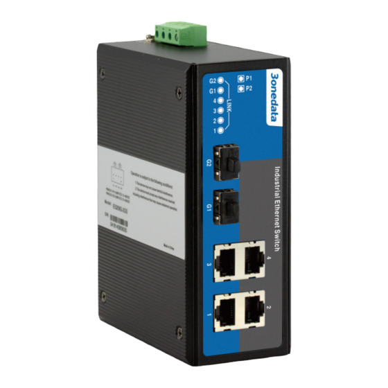
【LED Indicator】
LED indictor light on the front panel of product, the function of
each LED is described in the table as below.
LED
PWR1
System indication LED
State
Description
ON
Power 1 is working normally.
PWR1 is not connected or does not
OFF
run normally.
