- ページ 12
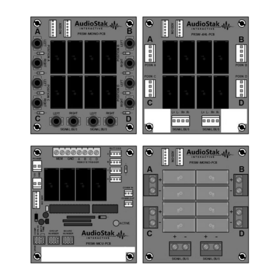
コントロールユニット AudioStak ProSwitch PRSW-4HL-PCBのPDF マニュアルと設置マニュアルをオンラインで閲覧またはダウンロードできます。AudioStak ProSwitch PRSW-4HL-PCB 20 ページ。

Signal Bus
Each ADD-ON module has signal connectors for each of its four Positions, as well as two sets of connectors for
the Signal Bus. When a Position is active, it is connected to the Signal Bus. Using the Signal Bus connectors, the
signal is carried from one ADD-ON module to the next so all are connected within its Group. Finally the Signal
Bus from that Group is connected to the Signal Bus in the next Group.
Consider the example of the most basic car stereo system: a head unit and a pair of speakers (see Figure 10).
The outputs of the head unit are wired directly to the terminals on the speakers. A ProSwitch system allows for
multiple products, arranged in Groups. The Signal Bus is equivalent to the direct wiring from the head unit to
the speakers in the first example. In the example ProSwitch system shown in Figure 10, only
Head Unit
Head Unit Group
Head Unit 1
Head Unit 3
Figure 10: Connecting Groups using the Signal Bus
Overview – Signal Bus
L+
L-
R+
SIGNAL WIRING
R-
Head Unit 2
Head Unit 4
SIGNAL BUS
Speaker Pair
L+
L-
R+
R-
Speaker Group
Speaker Pair 1
Speaker Pair 3
Speaker Pair 2
Speaker Pair 4
