- ページ 17
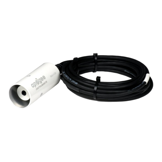
計測機器 Apogee Instruments SI-400 SeriesのPDF オーナーズマニュアルをオンラインで閲覧またはダウンロードできます。Apogee Instruments SI-400 Series 20 ページ。 Infrared radiometer

TROUBLESHOOTING AND CUSTOMER SUPPORT
Independent Verification of Functionality
The radiation detector in Apogee SI-100 series infrared radiometers is a self-powered device that outputs a voltage
signal proportional to the radiation balance between the detector and target surface. A quick and easy check of
detector functionality can be accomplished using a voltmeter with microvolt (µV) resolution. Connect the positive
lead of the voltmeter to the white wire from the sensor and the negative lead (or common) to the black wire from
the sensor. Direct the sensor toward a surface with a temperature significantly different than the detector. The µV
signal will be negative if the surface is colder than the detector and positive if the surface is warmer than the
detector. Placing a piece of tinfoil in front of the sensor should force the sensor µV signal to zero.
The thermistor inside Apogee SI-100 series radiometers yields a resistance proportional to temperature. A quick
and easy check of thermistor functionality can be accomplished with an ohmmeter. Connect the lead wires of the
ohmmeter to the red and green wires from the sensor. The resistance should read 10 kΩ at 25 C. If the sensor
temperature is less than 25 C, the resistance will be higher. If the sensor temperature is greater than 25 C, the
resistance will be lower. Connect the lead wires of the ohmmeter to the green and blue wires from the sensor. The
resistance should read 24.9 kΩ, and should not vary. Connect the lead wires of the ohmmeter to the red and blue
wires from the sensor. The resistance should be the sum of the resistances measured across the green and white
wires, and green and blue wires (e.g., 10 kΩ plus 24.9 kΩ at 25 C).
Compatible Measurement Devices (Dataloggers/Controllers/Meters)
SI-100 series radiometers have sensitivities in the microvolt range, approximately 20 to 60 µV per C difference
between target and detector (depending on specific model). Thus, a compatible measurement device (e.g.,
datalogger or controller) should have resolution of at least 3 µV (0.003 mV), in order to produce temperature
resolution of 0.05 C. Measurement of detector temperature from the internal thermistor requires an input
excitation voltage, where 2500 mV is recommended. A compatible measurement device should have the capability
to supply the necessary voltage.
An example datalogger program for Campbell Scientific dataloggers can be found on the Apogee webpage at
http://www.apogeeinstruments.com/content/Infrared-Radiometer-Analog.CR1.
Modifying Cable Length
When the sensor is connected to a measurement device with high input impedance, sensor output signals are not
changed by shortening the cable or splicing on additional cable in the field. Tests have shown that if the input
impedance of the measurement device is 10 MΩ or higher, there is negligible effect on the radiometer calibration,
even after adding up to 50 m of cable. Apogee model SI series infrared radiometers use shielded, twisted pair
cable, which minimizes electromagnetic interference. This is particularly important for long lead lengths in
electromagnetically noisy environments. See Apogee webpage for details on how to extend sensor cable length
(http://www.apogeeinstruments.com/how-to-make-a-weatherproof-cable-splice/). NOTE: For sensors with model
numbers lower than 7282, do not shorten the cable. There is a resistor built into the cable near the end that is
required for proper function. Please contact Apogee at [email protected] for instructions if
you must shorten the cable, or consult the circuit diagram on page 13 to replace the bridge resistor if the cable is
shortened.
