- ページ 7
リベット工具 Gage Bilt GB703VTのPDF インストレーション・マニュアルをオンラインで閲覧またはダウンロードできます。Gage Bilt GB703VT 15 ページ。
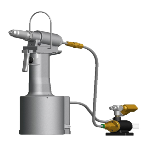
FILLING AND BLEEDING TOOL
NOTE:
Air Bleeder Assy (704153) is required.
WARNING:
Do not cycle tool without air bleeder assy (704153), or button head cap screw (402482) and stat-o-seal (S572) installed in
head cylinder assy (703109). Severe personal injury could result.
CAUTION:
Before filling handle assy (704132), air piston assy (704121) should be all the way down.
CAUTION:
When forcing piston rod assy (704138) downward, with head cylinder assy (703109) removed, hydraulic oil will eject
forcibly from handle assy (704132).
CAUTION:
Use CAUTION when removing screws and air bleeder assy (704153) hydraulic oil may be under pressure.
WARNING:
Failure to follow these instructions carefully may result in severe personal injury
IMPORTANT:
Be sure to use thread sealant on all hydraulic fittings, Loctite® 30534 or similar Teflon® infused pipe dope is
recommended.
Teflon may enter the hydraulic system and cause malfunction or damage. Use 1 1/2 wraps of tape on each thread. Cut
off all loose tape ends. Tighten until fitting feels snug and then go 1/2 to a full turn past that point.
tightening can easily distort the threads.
To replace a small amount of oil in the tool, remove button head cap screw (402482) and stat-o-seal (S572) from head cylinder assy
(703109) and attach the air bleeder assy (704153). Connect tool to air line and cycle ten times. Disconnect air, remove the air bleeder
assy (704153) and reinstall button head cap screw (402482) and stat-o-seal (S572) on head cylinder assy (703109). Torque button
head cap screw (402482) to 35-40 inch lbs. (Do NOT over-tighten). This will ensure the removal of any air from the hydraulic system
and its replacement with oil.
* FILLING & BLEEDING VIDEO AVAILABLE AT: www.gagebilt.com/bleeding.htm
Should it become necessary to completely refill the tool (such as would be required after tool has been dismantled and reassembled),
take the following steps after depressing actuator lever assy (704343)
1. Remove four button head cap screws (A-928). Remove the head cylinder assy (703109) from handle assy (704132). Slowly push
piston (703607) completely forward.
2. Fill handle assy (704132) and the oil passage on top of handle assy (704132) with automatic transmission oil, Dexron III or
equivalent. When looking at the top of the handle assy (704132), the oil passage is the hole that is counterbored for o'ring (S832).
3. Replace head cylinder assy (703109) with care, ensuring gasket (704129) and o'ring (S832) are properly installed. Tighten button
head cap screws (A-928) uniformly and torque to 40 inch lbs. to prevent leakage around gasket (704129).
4. Remove button head cap screw (402482) and stat-o-seal (S572) from the head cylinder assy (703109). Install air bleeder assy
(704153) and connect tool to air line. Cycle ten to fully circulate oil through hydraulic system.
5.
DISCONNECT AIR FROM
screw (402482) and stat-o-seal (S572) and torque 35-40 inch lbs. (Do NOT over-tighten).
6. Connect air supply. Cycle tool ten times and check stroke of .780 (19.8 mm) (see diagram below). We recommend using a pair
of dial calipers. With the actuator lever assy (704343) released, check dimension (A). With the actuator lever assy (704343)
depressed, check dimension (B). If stroke is not consistent within 1/64" (.0156) repeat bleeding steps 4-6.
1.145 (29.1mm)
S/N: 3157 AND ABOVE
PLEASE CONTACT GAGE BILT FOR ALL OTHER SERIAL NUMBERS.
CAUTION:
Teflon tape is an excellent thread sealer, however, if it is not properly applied, pieces of
TOOL. Remove air bleeder assy (704153) from the head cylinder assy (703109). Install button head cap
'A'
AND DISCONNECTING THE AIR SUPPLY:
.365 (9.3mm)
7
CAUTION:
Over
9/14