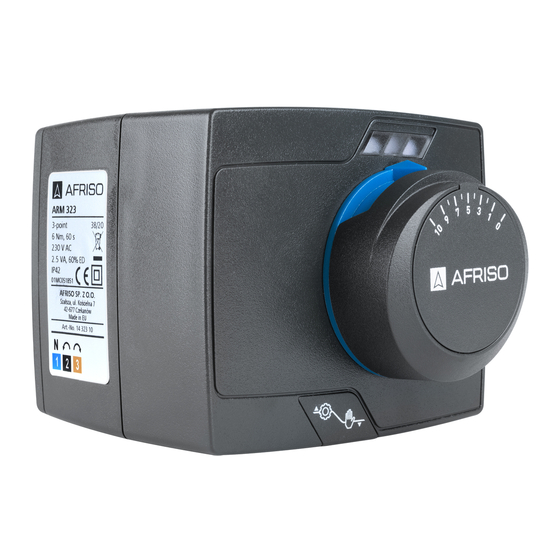
コントローラー AFRISO 14 343 10のPDF 取扱説明書をオンラインで閲覧またはダウンロードできます。AFRISO 14 343 10 2 ページ。

INSTRUCTION MANUAL
AFRISO Sp. z o.o.
Customer service
Szałsza ul. Kościelna 7
Tel. +48 330 33 55
42-677 Czekanów
Fax: +48 330 33 51
Poland
www.afriso.pl
NOTICE!
This instruction manual is also available on www.afriso.pl.
WARNING!
The product may only be mounted, commissioned and disposed of by quali-
fied, specially trained staff.
Alterations performed by unauthorized staff may cause a threat and are for-
bidden for safety reasons.
The product is powered by 230 V AC voltage. This may cause severe injuries
or death.
Do not let the product go into contact with water.
Before mounting the product please read the manual of the mixing valve.
APPLICATION
Electric actuators ARM ProClick are designed to operate on 3-/4-way rotary mixing valves, which requ-
ire a maximum turning torque of 6 Nm. They have a turning angle of 90˚. The ARM ProClick actuator
should be connected to a 3-point controller with a 230 V AC supply voltage. One can operate the actu-
ator also manually using the knob. The ARM ProClick actuators are mainly used to mix two streams via
the mixing valve, to obtain a set temperature on the outlet connection of the valve.
SCOPE OF DELIVERY
1. Electric actuator ARM ProClick with a knob, double-sided scale ("from 0 to 10" and "from 10 to 0")
and an electric cable with plug.
2. Mounting set for ARV valves without ProClick system (first generation) –
3. Instruction manual.
3. Slide the actuator on the mixing valve, so that the 4 pins of the ProClick mechanism find themselves
in the appropriate holes on the back of the actuator and the mechanism locks on them
The ProClick mechanism requires no tools.
Drawing 7. Mounting the ARM ProClick actuator
One can mount the actuator in 4 positions on the valve. The blue ring with indicator must point
upwards. If it does not, pull off the knob and blue ring. Then mount it back with the indicator pointing
upwards. The blue ring has a special hole inside to lift it with a flat screwdriver.
Drawing 8. Possible mounting positons
953.001.0061 1
Electric actuators ARM ProClick
Art.-No 14 323 10, 14 343 10, 14 343 11
not included in Art.-No 14 343
(Drawing
ARV ProClick valve
4 pins of the ProClick mechanism
flattening on the adapter
pushbutton of the ProClick mechanism
ARM ProClick actuator
ring with indicator
knob
double-sided scale
MOUNTING ON AN ARV ProClick VALVE
The ARM ProClick valve is factory set on 50% (position "5" on the scale). To mount the actuator pro-
perly on the valve, the valve must also be set on 50%.
1. Take off the knob and blue limiting ring from the ARV ProClick valve
pull the parts along the spindle axis. The knob construction allows to lift it with a flat screwdriver.
There are special holes on two sides of the knob.
Drawing 1. View on the ARV ProClick valve with removed knob
2. Set the valve on 50%, so that the sleeve inside the 3-way valve will be right in the middle between
the hot and cold inlets
(Drawing 2
connections in a 4-way valve
Drawing 2. 3-way, position 1
11.
cold
stream
Drawing 5. 3-way
1
2
3
4
4. Insert the double-sided scale in the correct position according to the opening/closing direction
7).
("from 0 to 10" or "from 10 to 0). Follow the rules below:
- if turning the knob right (clockwise) closes the valve, choose the scale "from 0 to 10",
- if turning the knob left (counter-clockwise) closes the valve, choose the scale "from 10 to 0".
The blue indicator should point at "5" on the scale. If not, please return to point 2.
5. Connect the actuator to the controller according to the scheme
(Drawing
10). The electric cable of the actuator can be detached.
This makes mounting and electrical connections easier. To take
out the plug, one must lift the lever of the cover and slide it out
(Drawing
11). Next detach the plug
into the socket only in one position.
Drawing 11. Detaching the cover
Connect the controller to the power supply according to the producer's manu-
al or guidelines.
Connect the neutral wire N direct to the mains supply or to the controller,
if it gives such a possibility.
(Drawing
or
Drawing
3,
Drawing
5) or just in the middle of the outlet
(Drawing
4,
Drawing
6).
Drawing 3. 3-way, positon 2
hot
stream
Drawing 6. 4-way
Drawing 9. View on two sides of the scale
(Drawing
12). The plug fits
Drawing 10. Electrical scheme
Drawing 12. Electrical plug
1). To do this, just
Drawing 4. 4-way
closing
direction
cold
stream
3-point
controller
actuator
wires
