- ページ 6
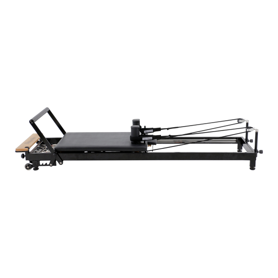
フィットネス機器 Align-Pilates H1 ReformerのPDF 組み立て説明書&取扱説明書をオンラインで閲覧またはダウンロードできます。Align-Pilates H1 Reformer 10 ページ。

3. Placing the bed in the frame and final assembly
Lower the foot bar to the position closest to the foot board. On the underside of the reformer bed note the
position of the fixed hook - see Fig.5. This hook runs beneath the wheel runner when in use and is there to
prevent the carriage from tipping - care must be taken to hook it under the runner as the bed is installed
into the frame. With assistance, lift up the carriage bed and flip it over, ensuring the springs are pointing
towards the foot bar. Now carefully lower the carriage bed into the
Fig.5
frame, taking care not to hit the frame, gently angle the bed so
that the hook passes beneath the runner of the frame. Once the
carriage bed is in position, gently slide the bed to the foot of the
reformer and attach one of the springs. On the opposite runner to
the hook is a second rotating hook. Rotate this to hold the bed in
place so the carriage cannot fall out when stood up. To remove
the carriage in future the rotating hook must be turned first and
then the bed lifted out at an angle, lifting the rotating hook side of
the reformer first.
Rotating Hook
Fixed Hook
4. Attaching & adjusting the rope risers
Partially unscrew the rope riser fastener on the end of the frame and insert the rope riser. Pull back on the
fastener and slide the rope riser to the desired height. When happy with the height, let go of the fastener
and twist to tighten, securing it in place. Be sure that the locking pin is engaged in one of the holes of the
rope riser to secure it safely in
position Fig.6 & 7. The H1 allows
you to set your ropes at 4 different
heights. To adjust the rope height
simply loosen the fastener then
pull out to release the pin. You can
then move the rope riser up or
down into one of the 4 holes. Fig.8.
Fig.6
Fig.7
Fig.8
5. Attach the Double Loop handles
Thread the nylon loop of the handle through the rope eyelet and then thread the loop handle through the
nylon eyelet to secure the handle to the rope as per Figs.9, 10 & 11. Pull tight to check it is secure.
Fig.10
Fig.9
Fig.11
6. Installing & locking the shoulder rests
Finally install the shoulder rests by sliding the chrome bar in to the receiver - see Fig.12. Once inserted the
shoulder rests lock in to place with a pin that is attached to the underside of the carriage which inserts
through the hole in the bottom of the chrome bar (Fig.13).
Fig.12
Fig.13
4
