- ページ 4
コントロールユニット Academy Audio Hi-End MUSESのPDF ユーザーマニュアルをオンラインで閲覧またはダウンロードできます。Academy Audio Hi-End MUSES 5 ページ。 Electronic volume controls

IMPORTANT: When de-energized, the muting relay RL1 disconnects the outputs from the audio output
circuitry and connects the board audio outputs to their respective common lines. It is recommended to
energize the muting relay after a small delay of about 1 second from the application of power to the
board.
Please refer to the MUSES®72320 volume control chip datasheet for detailed operation description. The
Volume Control board has the MUSES®72320 volume control chip hard wired with the chip select
address of 000.
7. Break-in Period
High-End audio enthusiasts are familiar with the "break-in" phenomenon: the sound gets better with
time. In engineering terms that refers to reduced distortions of the audio signal. This distortion
reduction may be attributed to priming of the capacitors and all the contacts in the audio path. A
noticeable sound improvement is expected after about 100 hours of listening.
8. Advanced Use of the Volume Control
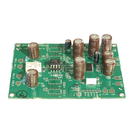
The Volume Control board is designed as a versatile "playground" for advanced users. The unique
properties of the MUSES®72320 volume control chip open extensive possibilities for sound quality
improvements.
Experimenting with Opamps.
Feel free to experiment with any +/-15V powered standard pinout dual JFET opamp using the provided
socket U2. It is also possible to use a SOIC-8 SMT dual opamp using a U3 footprint located under the
socket U2, when the socket is removed.
Use U4 and U5 footprints for +/-15V powered standard pinout dual JFET opamps, when only one
channel of each chip is used to improve channel separation. Install 0.1uF 50V 0805 capacitors in C32
and C33 footprints.
Use U6 and U7 footprints for +/-15V powered standard pinout single JFET opamps. Install 0.1uF 50V
0805 capacitors in C34 and C35 footprints.
To use bipolar input opamps in any of the mentioned above configurations, remove jumper resistors R8
and R14. Install quality polypropylene 1uF capacitors in C11 and C26 footprints, and 470K 0805 SMT
resistors in R6 and R16 positions. The resistor values may require tweaking depending on a type of an
opamp used. Do not use resistors below 150K.
For a completely passive volume control solution, remove the opamp from the socket U2 and connect
Tp1 to TP2, and TP5 to TP6. Remove resistors R10 and R13.Note, that the gain section of the MUSES
chip is unavailable in this mode and a high quality buffer should be used in the downstream circuitry.
Experimenting with Capacitors.
It is well-known that capacitors in the audio signal path affect sound quality. The Volume Control uses
high quality ELNA Silmic II electrolytic capacitors in the audio signal path circuitry.
Page 4 of 5
