- ページ 26
スイッチ Dell S6010-ONのPDF インストレーション・マニュアルをオンラインで閲覧またはダウンロードできます。Dell S6010-ON 46 ページ。
Dell S6010-ON にも: ファームウェア・リリース・ノート (12 ページ)

Figure 16. Ground wire and GND lug
1
1–ground wire
3
Install the second GND lug in compliance with NEC guidelines at the desired location on your rack to ground the switch.
a
Ensure that the rack mating surface is clean.
b Bring any bare metal to a bright finish.
c
Apply the anti-oxidant compound to the mating surfaces before mating.
SFP+ and QSFP+ optic installation
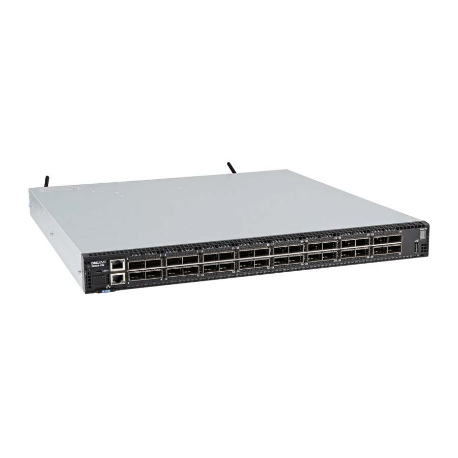
S6010–ON ports include 32 ports that function either as 40 GbE, or, using breakout cables, as a configuration of 96 ports of 10 GbE SFP+.
The 32 ports also include eight, ports 13–20, that are 40 GbE QSFP+.
For a list of supported optics, see the S6010-ON Specification Sheet at
CAUTION:
ESD damage can occur if the components are mishandled. Always wear an ESD-preventive wrist or heel ground strap
when handling the S6010-ON and its components.
WARNING:
When working with optical fibers, follow all the warning labels and always wear eye protection. Never look directly
into the end of a terminated or unterminated fiber or connector as it may cause eye damage.
1
Position the optic in the correct position. The optic key prevents it from being inserted incorrectly.
2
Insert the optic into the port until it gently snaps into place.
NOTE:
The top row of QSFP+ ports requires that you install the 40 GbE optics with the tabs facing up. The bottom row
of QSFP+ ports requires that you install the 40 GbE optics with the tabs facing down.
NOTE:
When you cable the ports, do not interfere with the airflow from the small vent holes preceding and below the
ports.
26
S6010–ON installation
2
2–GND lug
www.dell.com/support/
or contact your Dell representative.
