- ページ 6
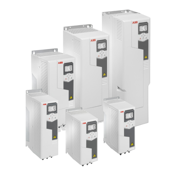
産業機器 ABB ACS580-01 drivesのPDF クイック・インストール&スタートアップ・マニュアルをオンラインで閲覧またはダウンロードできます。ABB ACS580-01 drives 17 ページ。 Frequency converter. nec types
ABB ACS580-01 drives にも: マニュアル (16 ページ), クイック・インストール&スタートアップ・マニュアル (17 ページ)

- 1. Install the Drive on the Wall
- 2. Remove the Cover(S)
- 3. Connection Procedure
- 4. Connect the Control Cables
- 5. Start up the Drive
- 6. Fieldbus Communication
- 7. Warnings and Faults
- 8. Terminal Data for the Power Cables
- 9. Ambient Conditions
- 10. Safe Torque off (Sto)
- 11. Related Documents
- 12. Declarations of Conformity
11. Connect the power cables
Connection diagram (shielded cables)
ACS580-01
L1
L2
PE
1
2
(PE)
PE
(PE)
L1
L2
1.
Two protective earth (ground) conductors. Drive safety standard IEC/EN 61800-5-1 requires two PE conductors, if
the cross-sectional area of the PE conductor is less than 10 mm
shield in addition to the fourth conductor.
2.
Use a separate grounding cable or a cable with a separate PE conductor for the line side, if the conductivity of the
fourth conductor or shield does not meet the requirements for the PE conductor.
3.
Use a separate grounding cable for the motor side, if the conductivity of the shield is not sufficient, or if there is no
symmetrically constructed PE conductor in the cable.
4.
360-degree grounding of the cable shield is required for the motor cable and brake resistor cable (if used). It is also
recommended for the input power cable.
5.
If necessary, install an external filter (du/dt, common mode, or sine filter). Filters are available from ABB.
Connection procedure
1.
Frames R5...R9: Remove the shroud(s) on the power cable terminals.
Frames R6...R9: Remove the side plates (a). Remove the shroud (b), then make the necessary holes for the cables. In
frames R8...R9, if you install parallel cables, also make the necessary holes in the lower shroud.
R5
1
R+
L3
R-
UDC+
4
L3
R6...R9
1a
T1/U T2/V T3/W
4
5
3
V1
U1
W1
PE
M
3
2
2
Cu or 16 mm
Al. For example, you can use the cable
R6...R9
1b
Frames R1...R3 have a built-in brake
chopper. If necessary, you can con-
nect a brake resistor to terminals R-
and UDC+/R+. The brake resistor is
not included in the drive delivery.
In frames R4...R9, you can connect
an external brake chopper to termi-
nals UDC+ and UDC-. The brake
chopper is not included in the drive
delivery.
6
