- ページ 10
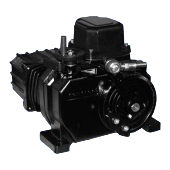
コントローラー ABB Contrac PME120AIのPDF 取扱説明書をオンラインで閲覧またはダウンロードできます。ABB Contrac PME120AI 20 ページ。 Electrical part-turn actuator
ABB Contrac PME120AI にも: 取扱説明書 (18 ページ)

3
cone 1 : 10
Fig. 3: Dimensional drawing
1. Output lever
2. Link tube
3. Ball-and-socket joint
4. Welding bushings (C15 to DIN 17210)
5. Counter nuts
6. Crown nuts
8
Electrical Connection
Proper actuator operation requires an actuator specific software loaded in this associated electronic
unit. Compare the data labels on both, electronic unit and actuator, in order to ensure a correct hard-
ware and software assignment.
8.1 Integrated electronic unit (standard)
Power and signal cables are connected to the integrated electronic unit via a plug.
mains
(single
phase)
Fig. 4: Electrical connection, standard
The following steps must be performed to switch the actuator to automatic mode (AUT):
- Activate digital inputs DI 1, DI 2 and DI 3 via the configuration program.
- Make sure that the supply voltage is present on digital input 1 (DI 1).
- Activate AUT mode via the configuration program.
10
Electrical Part Turn Actuators for Continuous Modulating Control PME120AI (Contrac)
62 - 78
4
5
6
14
ext.
fuse
L
N
DI1
DI2
MAN/AUT MAN (+)
1
13
3
4
5
6
+
- +
- +
L
L - 140
2
4
M14 x 1.5
left / right
Sub Distribution Board
DI3
DO1
DO2
DO3
MAN (-)
ok/fault
end 0%
end 100%
7
8
17
18
19
20
15
16
-
Contrac Actuator
Electrical Connection
62 - 78
3
5
1 6
setpoint
Uv
act. value
+ HART
0/4..20 mA
0/4..20 mA
21
22
23
9 10
11
12
+
-
-
+
+
-
RB
I
24V
+ -
U
r00305x1
transmitter
4..20 mA
1
2
+
RB
+ -
Uv
24V
(Option)
r00295e2
A68-2005-003 EN
