- ページ 2
ネットワーク・ハードウェア Cisco PIX 525のPDF ユーザーマニュアルをオンラインで閲覧またはダウンロードできます。Cisco PIX 525 30 ページ。 Security appliance
Cisco PIX 525 にも: データシート (13 ページ)

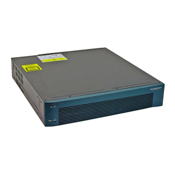
PIX 525 Product Overview
Figure 6-2
Figure 6-2
There are two LEDs on the front panel of the PIX 525 (see
Figure 6-3
Table 6-1
Table 6-1
LED
POWER
ACT
There are three LEDs for the each RJ-45 interface port and three types of fixed interface connectors on
the back of the PIX 525.
Cisco PIX Security Appliance Hardware Installation Guide
6-2
shows the rear view of the PIX 525.
PIX 525 Rear Panel
100Mbps ACT
LINK
100Mbps ACT
LINK
10/100 ETHERNE T 1
10/100 ETHERNE T 0
PIX 525 Front Panel LEDs
lists the state of the PIX 525 front panel LEDs.
PIX 525 Front Panel LEDs
Color
State
Green
On
Green
On
Off
F
A
I
L
O
V
E
R
PIX-525
USB
CONSOLE
Figure
Description
On when the unit has power.
On when the unit is the active failover unit.
Off when the unit is in standby mode.
Chapter 6
6-3).
78-15170-02
PIX 525
