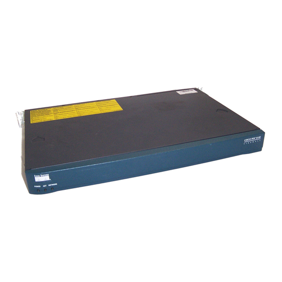
- ページ 4
ネットワーク・ハードウェア Cisco PIX-515EのPDF クイック・スタート・マニュアルをオンラインで閲覧またはダウンロードできます。Cisco PIX-515E 42 ページ。 Security appliance
Cisco PIX-515E にも: クイック・スタート・マニュアル (42 ページ)

2
Install the PIX 515E
DMZ server
Laptop
computer
Printer
Follow these steps to install the PIX 515E:
Install the rubber feet
Step 1
The chassis is also rack-mountable. For rack-mounting and failover instructions, refer to
Note
the
Cisco PIX Firewall Hardware Installation Guide.
Use the yellow Ethernet cable (72-1482-01) provided to connect the outside 10/100 Ethernet
Step 2
interface, Ethernet 0, to a DSL modem, cable modem, or switch.
Use the other yellow Ethernet cable (72-1482-01) provided to connect the inside 10/100
Step 3
Ethernet interface, Ethernet 1, to a switch or hub.
Connect the power cable to the rear of the PIX 515E and a power outlet.
Step 4
Power up the PIX 515E. The power switch is located at the rear of the chassis.
Step 5
For additional hardware installation procedures, refer to the
Note
Installation Guide.
4
Switch
DMZ
Switch
Inside
Personal
computer
onto the five, round, recessed areas on the bottom of the chassis .
PIX 515E
Outside
Power
Router
Internet
cable
Cisco PIX Firewall Hardware
