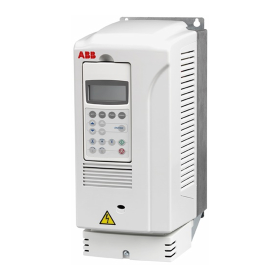
- ページ 12
コントロールユニット ABB ACS 800 SeriesのPDF ユーザーマニュアルをオンラインで閲覧またはダウンロードできます。ABB ACS 800 Series 14 ページ。 Converter modules with electrolytic dc capacitors in the dc link
ABB ACS 800 Series にも: 設置に関する注意事項 (2 ページ), マニュアル (16 ページ)

5 — Explanation of Calculations
Pump operating point
Pump drive calculations
In this chapter, the formulas behind PumpSave calculations are presented. The
formulas use metric units. If the user enters the data in US units, PumpSave
converts it to metric units first. The conversion factors are given in the end of
this manual.
The formula for the pump curve estimate used in calculations is:
H
H
pi
max
This might be somewhat erroneous to submersible and high characteristic
speed pumps etc.
Respectively, the system curve used in calculations is
H
H
si
st
Q
A pump will always operate where these curves intersect, as Graph 1 shows.
Please notice that the point defined by H
valid for pump and system curve.
PUMP
H
max
H
N
H
dyn
H
st
Graph.1. Typical pump and system curves.
When adjusting the pump speed to control the volume flow, the process moves
via system curve Hsi. Respectively, when throttling the pipeline the pump
operates continuously at the same speed, and the movement of the process is
via pump curve Hpi.
The nominal shaft power of a pump is calculated from the formula
2
Q
i
H
H
max
n
Q
n
2
Q
i
H
H
n
st
n
SYSTEM
Q
N
and Q
is assumed to be known and
n
n
system curve, H
=H
+(Q
/Q
si
st
i
pump curve, H
=H
pi
max
2.
)
(H
-H
)
n
n
st
2 .
-(Q
/Q
)
(H
-H
)
i
n
max
n
12
