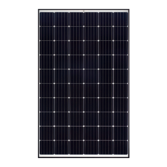
Astronergy CHSM6612M 설치 매뉴얼 - 페이지 15
{카테고리_이름} Astronergy CHSM6612M에 대한 설치 매뉴얼을 온라인으로 검색하거나 PDF를 다운로드하세요. Astronergy CHSM6612M 18 페이지. Crystalline silicon pv
Astronergy CHSM6612M에 대해서도 마찬가지입니다: 설치 매뉴얼 (10 페이지), 설치 매뉴얼 (12 페이지), 설치 매뉴얼 (12 페이지), 설치 매뉴얼 (19 페이지), 매뉴얼 (19 페이지)

Depending on the maximum rated fuse current of
the PV module and the local electrical installation
standards, the connection of parallel strings of PV
modules needs to be equipped with suitable fuses
or preventive diodes for circuit protection purposes.
6.2 Electrical connection
To ensure the normal operation of the system, make
sure the polarity of cables is correct when connecting
modules or loads, such as inverters and batteries. If the
PV module is not connected correctly, the bypass
diode may be damaged. Fig. 14 shows how the PV
modules are connected in series and parallel. PV
modules can be wired in series to boost the voltage.
Series connections are made by connecting the wire
from the positive terminal of one module to the
negative terminal of the next module. PV modules can
be wired in parallel to increase the current by
connecting the positive terminal of one module to the
positive terminal of the next module. If a module is not
connected correctly, the bypass diode may be
damaged.
15
Fig. 14 Schematic diagram of electrical connection
!ATTENTION
If one PV module string (or PV array) is connected
to another with opposite polarity, irreversible
damage can be caused to the PV module product.
Be sure to confirm the voltage and polarity of each
string before making a parallel connection. If
measurements reveal opposite polarity or a voltage
difference greater than 10V between the strings,
check
their
structural
proceeding with the connection.
The number of modules connected in series and
parallel should be reasonably designed according to
the system configuration.
PV modules with different electrical performance
models cannot be connected in one string.
The system shall use special cables and connectors
for PV system and ensure that all connections are
securely fastened. The cable must be 4mm
AWG) and withstand the maximum possible
open-circuit voltage of the PV system.
When fixing the cable to the rack, it is necessary to
avoid mechanical damage to the cable or to the PV
configuration
before
2
(i.e. 12
