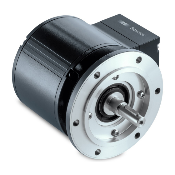
Baumer Hubner Berlin PMG 10 설치 및 운영 지침 매뉴얼 - 페이지 18
{카테고리_이름} Baumer Hubner Berlin PMG 10에 대한 설치 및 운영 지침 매뉴얼을 온라인으로 검색하거나 PDF를 다운로드하세요. Baumer Hubner Berlin PMG 10 36 페이지. Absolute encoder with magnetic sensing
Baumer Hubner Berlin PMG 10에 대해서도 마찬가지입니다: 설치 및 운영 지침 매뉴얼 (48 페이지)

ELECTRICAL CONNECTION / LED FUNCTION DISPLAyS
5.4
LED function displays
LED
INC1
(additional output
incremental 1)
INC2
(additional output
incremental 2)
Status
Speed
5.5
Speed switch - Switching characteristics
Event
During initialisation
After initialisation and
speed ≤ -ns (off)
-ns (off) < speed ≤ -ns (on)
-ns (on) < speed < +ns (on)
+ns (on) ≤ speed < +ns (off)
+ns (off) ≤ speed
High resistance
Resistance between
SP+ and SP-
Low resistance
n
= Speed
+ns (on) = Activation speed at shaft rotation in positive rotating direction*
+ns (off) = Deactivation speed at shaft rotation in positive rotating direction*
-ns (on) = Activation speed at shaft rotation in negative rotating direction*
-ns (off) = Deactivation at shaft rotation in negative rotating direction*
*
See section 6, page
15/33
Red
Undervoltage
Overload
Over-temperature
Undervoltage
Overload
Over-temperature
Internal error
Speed higher switching speed
(overspeed)
-n
-ns (off)
25�
State of the speed switch output
High resistance (overspeed)
High resistance (overspeed)
State unchanged
Low resistance (no overspeed) after initialisation if
the encoder is rotating between the switching range
during initialisation�
Low resistance (no overspeed)
State unchanged
Low resistance (no overspeed) after initialisation if
the encoder is rotating between the switching range
during initialisation�
High resistance (overspeed)
-ns (on)
0
MB245EN - 11171693, 17A2, Baumer_PMG10-SSI_II_EN
Green
OK
OK
OK
Speed lower switching speed
+ns (on)
+ns (off)
+n
