AMS AS5601 매뉴얼 - 페이지 5
{카테고리_이름} AMS AS5601에 대한 매뉴얼을 온라인으로 검색하거나 PDF를 다운로드하세요. AMS AS5601 13 페이지. Usb interface & programming box
AMS AS5601에 대해서도 마찬가지입니다: 운영 매뉴얼 (12 페이지), 사용자 설명서 (13 페이지)

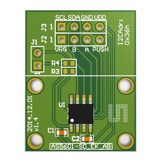
AS5601 Adapter Board
Figure 2:
Mechanical Configuration
The magnet should be aligned by reading the output of the AGC register of the AS5601. For optimal
alignment, the AGC value is in the middle of the AGC range.
Note: If the magnetic field seen by the AS5601 is below 8mT, the output is disconnected and
permanent angle programming is not possible. The AB output will not show any change until the
magnet is present again.
5.1 Electrical Setup
The Adapterboard can be used in 5V or in 3.3V mode in the configurations shown below. Short J1
to operate in 3.3V mode.
2
5.1.1 I
C Mode
Using the I2C Interface, all functions of the AS5601 can be configured and permanently
programmed. Additionally the output and a raw angle (unmodified value) can be read from the
output registers.
Figure 3:
Using the board in I2C mode
µC
ams Eval Kit Manual, Confidential
[v1-00] 2014-Jul-31
+
-
SDA
SCL
Magnet Holder (non-magnetic)
Sensor Magnet (d6x2,5)
AS5601
PCB
Document Feedback
Page 5
