Anritsu Company VectorStar ME7848A-0240 빠른 시작 매뉴얼 - 페이지 8
{카테고리_이름} Anritsu Company VectorStar ME7848A-0240에 대한 빠른 시작 매뉴얼을 온라인으로 검색하거나 PDF를 다운로드하세요. Anritsu Company VectorStar ME7848A-0240 17 페이지. Opto-electronic network analyzer systems
Anritsu Company VectorStar ME7848A-0240에 대해서도 마찬가지입니다: 빠른 시작 매뉴얼 (15 페이지)

3. System Check
Consult the ME7848A/E Technical Data Sheet – 11410-01145 for more information on the amount of dynamic
range/noise floor improvement possible with the 'reversed' vs. the 'normal' coupler arrangement, but it is
generally on the order of 10 dB at low frequencies, decreasing to 0 dB slightly above 40 GHz.
Figure 4.
Rear Panel: 'Normal' (left) and 'Reversed' (right) Configurations (for 40 and 70 GHz systems)
Figure 5.
Front Panel: 'Normal' (left) and 'Reversed' (right) Configurations (for 40 and 70 GHz systems)
3.
System Check
Initial Settings
1. Begin with the VNA in a Preset state and then set up for the measurement:
a. Set test port power to +5 dBm (POWER Menu) for -0240 systems and -10 dBm for the -021x and
-027x systems.
b. Set IFBW to 100 Hz (AVERAGING menu).
c. Set the frequency range from 70 kHz to 40/70/110 GHz (for -0240, -027x or -021x systems,
respectively) with 201 points.
d. Set up one trace to display S21 in log mag form.
2. Connect the RF cables from the accessory kit to the VNA ports (uses the FF adapter on port 2).
Module/VNA ports may be used as well.
3. Perform a full 2-port SOLT (or broadband cal for -021x systems) calibration of the VNA at the cable ends
(see the VectorStar Calibration and Measurement Guide if more information is needed on this).
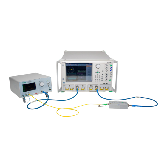
4. Make all connections to form the opto-electronic system as outlined in the previous section (port 1 cable to
the E/O converter, port 2 cable to the O/E module, fiber patch cord between the E/O and O/E devices).
The O/E module should be powered up and warmed up. The E/O converter should be powered up but the
laser still off.
QSG-8
PN: 10410-00777 Rev. C
ME7848A/E QSG
