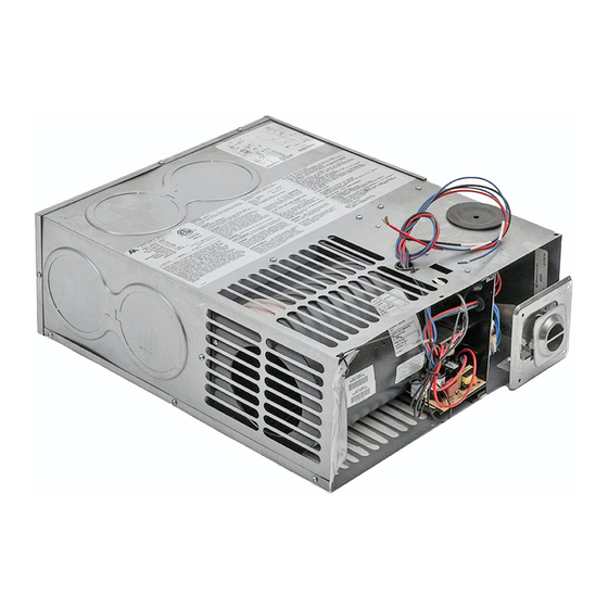
Atwood AFMD35 기술 설치 매뉴얼 - 페이지 5
{카테고리_이름} Atwood AFMD35에 대한 기술 설치 매뉴얼을 온라인으로 검색하거나 PDF를 다운로드하세요. Atwood AFMD35 19 페이지. Afm series hydro flame

DUCTING OPTIONS
REQUIRED MINIMUM DISCHARGE
Models
AFM (16)(20)
AFM (25)(30)
AFM (35)
Models using bottom discharge options
Models using vertical discharge options
Proper duct installation is critical to operation of furnace. When
installing ducts, use materials rated for continuous use at 200°F.
See minimum clearance to floorboards, walls & similar combustible
building materials.
Each 4-inch duct opening provides 12 in
2
an extra 12 in
of non-closeable duct discharge area for each
closeable register used.
Use of 2" ducting does not count toward achieving minimum
discharge requirements. Ducting into dead air space with no return
air, such as holding tank areas, does not count toward achieving
minimum discharge requirements.
Adjust ducting installation to obtain air rise of 100°F-130°F.
Horizontally installed furnaces – using side duct options – must
have a minimum of one duct from both left and right side of casing.
FLEXIBLE DUCTING SYSTEMS
When designing flexible duct systems:
Avoid sharp bends or crushed ducts.
Stretch all ducts and run them directly to outlets, keeping quantity
and angles of bends to a minimum.
1.
Remove knockout plates from desired outlets.
2.
Attach a duct adapter to each opening by inserting flange over
casing, locking the tab into casing slot and turning adapter 90°.
3.
Attach and secure four-inch flexible ducts to adapters.
4.
Run ducts to desired location within RV, secure to registers.
5.
Additional ducting may be needed to maintain correct static
pressure.
Figure 5
HARD DUCT FLOOR SYSTEMS
When designing hard ducting systems:
Undersized ducting will cause high temperature limiting.
Oversized ducting will cause inadequate air flow from registers.
Required Discharge Area
2
24 in
2
36 in
2
36 in
2
48 in
2
48 in
2
of discharge area. Provide
5
When hard ducting is 1-1/2" in depth, an additional flex duct may be
needed to maintain installation duct air flow requirements.
DO NOT install floor registers within 2 feet of return air openings.
See ducting option from casing top and bottom areas. These
options can be with flex ducting or by hard ducting installations.
Hard ducting must be sealed to insure proper operation of the
appliance.
HORIZONTAL OR VERTICAL BOTTOM DISCHARGE
Units can be installed as bottom or vertical bottom discharge
systems. See figure 6 for cutout location and sizes.
1.
Remove bottom discharge knockout or side cover plate, these
ducting options must be connected to a ducting system.
2.
Insure sealing of all joints when use of a gasket and plenum plate
for hard ducting configurations.
3.
Other methods of sealing furnace to the floor are acceptable as long
as clearances and seals meet requirements of clearances and
temperature.
4.
Fasten plenum plate over floor cutout. If a gasket and plenum plate
is not used seal furnace to hard duct system making sure seal is
airtight.
5.
Position gasket on plenum over hole opening see Figure 6.
6.
Set furnace on gasket; make sure gasket remains in position.
7.
Additional ducting can be used to maintain correct air flow and
temperature rise.
FLEX ADAPTER PLATE
A flex adapter may be used to provide more flexibility for alignment
of discharge opening on hard duct systems. This system can be
used on all models installed horizontally providing ducting from rear
of furnace without using side ducts. Use of a flexible mounting plate
kit is available. See parts list.
1.
Cut a 4" x 12" opening over floor ducting.
2.
Remove three knockouts from rear of furnace.
3.
Install duct adapters in each opening see Figure 7.
4.
Place flex adapter plate with foam tape against hard ducting making
sure openings line up.
5.
With plate held in place, fasten plate to ducting using screws or
staples as need to keep it flat.
6.
Install three duct adapters into flex adapter plate.
7.
Attach flexible ducting from furnace to flex adapter plate and secure
ducting in place on both ends.
Figure 6
Figure 7
