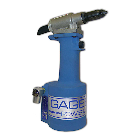
Gage Bilt GB703SR8VT 매뉴얼 - 페이지 10
{카테고리_이름} Gage Bilt GB703SR8VT에 대한 매뉴얼을 온라인으로 검색하거나 PDF를 다운로드하세요. Gage Bilt GB703SR8VT 15 페이지. Installation tool

HEAD
WARNING:
Dispose of Hydraulic Oil in accordance with applicable regulations.
Remove nose assembly and adapter from tool before attempting disassembly of head assy.
Remove end cap (703114). Push against threaded end of piston (703607) to slide it out of head cylinder assy (703134). Be careful not
to damage threads or cause burrs on polished piston rod assy (744136) surface.
The re-assembly sequence is the opposite of disassembly. (See Filling and Bleeding instructions.) Apply Loctite #242 and torque the
socket head cap screws (400061 and 400066) uniformly to 40 inch lbs. to prevent leakage around the gasket (704129).
703013 - DRAWBOLT EXTENSION
70856 - JAM NUT
703007 - SLEEVE EXTENSION
703134 - HEAD CYLINDER
ASSY
S832 - O'RING
704129 - GASKET
402482 - B.H.C.S.
S572 - STAT-O-SEAL
744306
MANIFOLD-HEAD
ASSY
704130
AIR ACTUATOR
ASSY
SOCKET HEAD
CAP SCREW (2)
703011 - TUBE
204304 - SWIVEL ASSY
(INCLUDES 401080 & 403764)
HYDRAULIC HOSE
400066
SOCKET HEAD
400061
CAP SCREW (2)
S834 - O'RING
401089 - BACK-UP RING
S834 - O'RING
401816 - PLUG
A-317
724017 LEVER
ASSY
S572 - STAT-O-SEAL (2)
10
400788 - O'RING
S829 - O'RING
400788 - O'RING
405865 - POLYSEAL
703607 - PISTON
204304 - SWIVEL ASSEMBLY
401080 - BACK-UP RING
703560 - HOSE GUARD (NOT SHOWN)
704311 - AIR LINE
A-144 - HOSE CLAMP (2)
S1181 - BARBED FITTING (2)
744303 - MANIFOLD-HANDLE
402482
BUTTON HEAD
CAP SCREW (2)
403764 - O'RING
A-663 - HANGER
REV. 10/14
