Gage Bilt GB740 원본 사용 설명서 - 페이지 7
{카테고리_이름} Gage Bilt GB740에 대한 원본 사용 설명서을 온라인으로 검색하거나 PDF를 다운로드하세요. Gage Bilt GB740 20 페이지.
Gage Bilt GB740에 대해서도 마찬가지입니다: 설치 매뉴얼 (12 페이지)
When the actuator is depressed, the pressurized air inside of the tool is released allowing spring pressure to move the valve spool
assembly causing the air to be redirected. The air is directed to the top of the air piston assembly, moving it in a downward direction.
The air below the air piston assembly is then directed through the valve sleeve and exhausted out of the bottom of the tool. Simultaneously,
the piston rod assembly, connected to the air piston assembly, is also moving down, forcing hydraulic oil up and into the front side of
the head cylinder, causing the piston assembly to move to the rear of the head cylinder. The internal components of the attached nose
assembly are also moving with the piston assembly to start the fastener installation. When the fastener installation is completed, the
actuator is released. Air pressure is then built up inside of the handle assembly causing the valve spool assembly to return to its
original position and reversing the sequence directing air pressure to the rear of the head cylinder, causing the piston assembly to
move to the forward position.
Piston Travel
Air exhaust
Piston Rod Assembly
moves down
Air Piston
moves down
GB740 S/N 1175 AND ABOVE
PLEASE CONTACT GAGE BILT FOR ALL OTHER SERIAL NUMBERS.
PRINCIPLE OF OPERATION
PULL Cycle
Air exhaust
Pressurized Oil
Unpressurized Oil
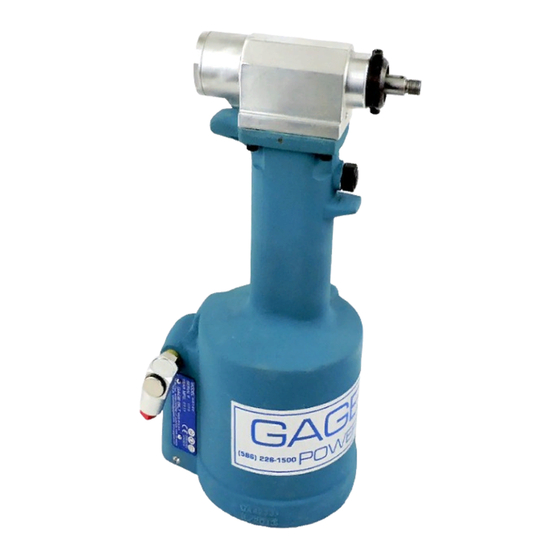
Image may not reflect actual tool
Piston Rod Assembly
moves up
Air Piston
moves up
Pressurized Air
Unpressurized Air
7
RETURN Cycle
Piston Travel
Air exhaust
Rev. 5/22