Autonics BWML Series 빠른 시작 매뉴얼 - 페이지 2
{카테고리_이름} Autonics BWML Series에 대한 빠른 시작 매뉴얼을 온라인으로 검색하거나 PDF를 다운로드하세요. Autonics BWML Series 5 페이지. Line-deam mapping sensors
Cautions during Installation
• Be sure to install this product by following the usage environment, location, and
specified ratings. Consider the listed conditions below.
- Installation environment and background (reflected light)
- Sensing distance and sensing target
- Direction of target's movement
- Feature data
• When installing multiple sensors closely, it may result in malfunction due to mutual
interference. Install it by referring to the interference protection and the installation
method in the manual.
• Do not use in places where the light-receiving sensor is exposed to direct sunlight or
where the ambient illumination is higher than the specification.
• Do not impact with a hard object or bend the cable excessively. That could decrease
the product's water resistance.
• Use this product after the test. Check whether the indicator works appropriately for
the positions of the detectable object.
Ordering Information
Thisisonlyforreference,the actual product does not support all combinations.
Forselectingthespecifiedmodel,followtheAutonicswebsite.
BWML
❶
-
❷
CL
❶ Sensing target pitch
Number: Optical axis pitch (≥ 20 mm)
❸ Operation mode
L: Light ON
D: Dark ON
Product Components
• Product × 1
• Instruction manual × 1
Output Connector
• 4-pin connector: TS04515B0000G (green), TS04510B0000G (black) (5.08 mm pitch)
• Connector socket specification: Contact the manufacture for the socket and cable.
Specifications
Connector socket (4-pin, green) OQ0455510000G
Connector socket (4-pin, black)
OQ0455010000G
❸
-
❹
❷ Sensing CH
Number: 4 to 62 CH
❹ CH ordering orientation
No-mark: Forward (bottom = 1 CH)
R: Backward (top = 1 CH)
• Bracket A × 4
• Bracket B × 4
• Fixing bolt × 8
Manufacture
ANYTEK
ANYTEK
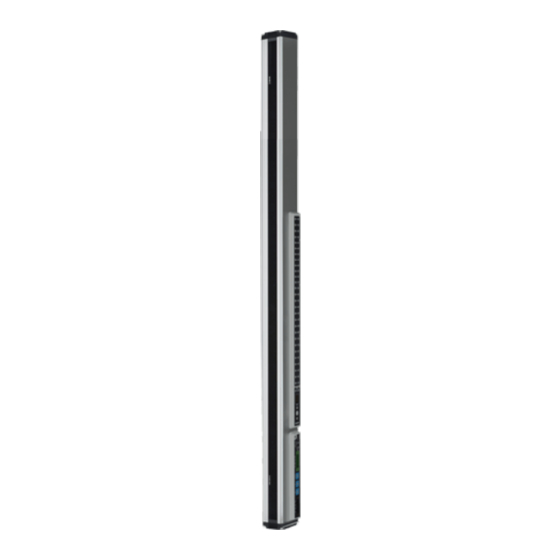
Dimensions
• Unit: mm, For the detailed drawings, follow the Autonics website.
• Length of the product can be different by its ordered specification.
Refer to the followings
Max. sensing area = 20+{sensing target pitch×(the total number of sensing target-1)}
34.5
41.5
■ Bracket A
2-R2
Ø7
4-R1.1
2-R2
Ø24
4-R1.6
R2
15
30
Connections
■ Power cable connector
Pin
Cable
Connector
Func.
no.
color
ⓐ
Black
SET
ⓐ
ⓑ
Brown
VCC
ⓑ
ⓒ
ⓒ
Blue
GND
ⓓ
ⓓ
Yellow
F.G.
Length of the
Max. sensing area
product (L)
(mm)
384
280
434
310
484
335
564
460
614
490
664
515
744
640
794
670
844
695
924
820
974
850
1024
875
1104
1000
1154
1030
1204
1055
1284
1180
1334
1210
1384
1235
1464
1360
1514
1390
1564
1415
1644
1540
1694
1570
1744
1595
1824
1720
1874
1750
1924
1775
■ Bracket B
2-R2
Ø7
4-R1.6
2-R2
Ø24
4-R1.1
R2
15
30
■ Comm. connector
Pin
Cable
Connector
no.
color
ⓔ
Blue
ⓕ
White
ⓖ
Yellow
ⓔ
ⓕ
ⓖ
ⓗ
Black
ⓗ
Func.
DA
DB
DG
SLD
(Shield)