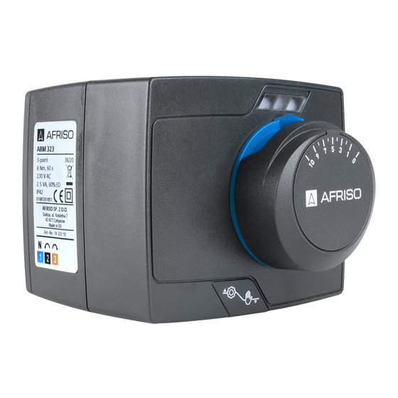
AFRISO ARM ProClick 사용 설명서
{카테고리_이름} AFRISO ARM ProClick에 대한 사용 설명서을 온라인으로 검색하거나 PDF를 다운로드하세요. AFRISO ARM ProClick 2 페이지.
AFRISO ARM ProClick에 대해서도 마찬가지입니다: 사용 설명서 (2 페이지)

INSTRUCTION MANUAL
AFRISO Sp. z o.o.
Zespół Obsługi Klienta
Szałsza, ul. Kościelna 7
tel. 32 330 33 55
42-677 Czekanów
fax 32 330 33 51
www.afriso.pl
NOTICE!
This instruction manual is also available on www.afriso.pl.
WARNING!
The product may only be mounted, commissioned and disposed of by qualified, specially
trained staff. Electrical work should always be entrusted to a qualified electrician.
Alterations performed by unauthorized staff may cause a threat and are forbidden
for safety reasons.
The product is powered by 230 V AC or 24V AC voltage. This may cause severe injuries
or death.
Do not let the product go into contact with water.
Do not alter the product in any way.
Before mounting the product please read the manual of the mixing valve.
APPLICATION
Used in water-based heating and cooling systems, can be mounted on 3- and 4-way mixing valves.
When connected to an appropriate controller, ARM 3-point actuators are used to mix two streams via
the mixing valve, and ARM 2-point actuators are used to switch the stream between two connections.
The ARM proportional actuator can be controlled, depending on the settings, with 0..10 V, 2..10 V, 0..20 mA,
4..20 mA or PWM signals and serve any function.
SCOPE OF DELIVERY
1. ARM ProClick electric actuator with a knob, double-sided scale ("from 0 to 10" and "from 10 to 0") and
an electric cable with a plug.
2. Instruction manual.
3. Mixing valve mounting manual.
ELECTRICAL CONNECTIONS
Make electrical connections in the controller depending on the version of the actuator.
The version is marked on the nameplate on the actuator housing.
3-point control actuator
Connect the actuator to the controller
according to the diagram
The neutral wire of the actuator should
be connected to the corresponsive clamp
on the controller, or directly into the
mains neutral wire.
After making the connections, check
whether the actuator turns in the
required direction.
If needed, swap wires 2 and 3.
2-point control actuator
The neutral wire of the actuator needs to be connected into the mains
neutral wire. Detach the knob and set the switch
to the diagram
(Fig.
required actuator rotation direction (example found on
Fig. 7. Electrical diagram of a 2-point actuator, switching function
953.011.0129
ARM ProClick
electric actuators
3-point
(Fig.
6).
controller
Actuator wires
Fig. 6. Electrical diagram
of a 3-point actuator
(Fig.
8.) according
7.). Next, connect the wires depending on the
page
6).
2-point
2-point
controller
controller
Actuator wires
Actuator wires
CONSTRUCTION
Fig. 1. Construction of the ARM ProClick actuator
The actuator can be mounted on the valve in four different positions. The blue ring with indicator must
point upwards. If it does not, pull off the knob and blue ring. Then mount it back with the indicator poin-
ting upwards. The blue ring has a special hole inside, allowing it to be lifted with a flat headed screwdriver.
Fig. 2. Possible mounting positions and set-
ting the ring with the pointer and the scale
The actuator power cable can be detached, which simplifies mounting and electrical work. To detach
the actuator plug, lift the lever of the cover and slide it out of the actuator housing
to take out the plug
(Fig.
5.). The plug fits into the socket in only one position.
Fig. 4. Detaching the
1
2
page
3
4
ELECTRICAL CONNECTIONS
Fig.8. Actuator rotation direction switch
An example for 2-point control
When the switch
(Fig.
8.) is set to the
, position, and voltage is applied to the black
wire (2), the actuator will turn the valve
counterclockwise to the end position. When
voltage is applied to both the black (2) and
brown (3) wires, the actuator will turn the valve
clockwise to the other end position.
ProClick system disconnecting pushbutton
ARM ProClick electric actuator
ring with indicator
double-sided scale
Fig. 3. Improper mounting position
cover lid
2 and 3-point control actuator
Actuators marked like this can work as either 3-point
or 2-point actuators.
To use the device in the 3-point mode, you need to:
Connect the actuator with a controller as shown in the
diagram on
Fig. 6.
After making the connections, check if the actuator turns
in the direction required. If needed, swap wires 2 and 3.
To use the device in the 2-point mode, you need to:
Connect the neutral wire of the actuator directly to the mains
neutral wire. Detach the knob and set the switch
according to the diagram
(Fig.
7.). Next, connect the wires
depending on the required actuator rotation direction.
When the switch
(Fig.
8.) is set to the
position, and voltage is applied to the brown
wire (3), the actuator will turn the valve
clockwise to the end position. When voltage
is applied to both the brown (3) and black
(2) wires, the actuator will turn the valve
counterclockwise to the other end position.
knob
(Fig.
4.). Then proceed
Fig 5. Electrical plug
(Fig.
8.)
,
