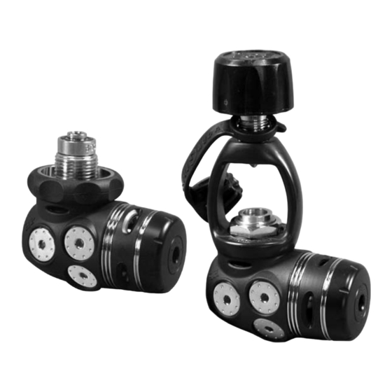
Aqua Lung Legend First Stage 기술 유지보수 매뉴얼 - 페이지 9
{카테고리_이름} Aqua Lung Legend First Stage에 대한 기술 유지보수 매뉴얼을 온라인으로 검색하거나 PDF를 다운로드하세요. Aqua Lung Legend First Stage 18 페이지.

Legend First Stage Technical Maintenance Manual
c. Remove the first stage from the vise. Hold the first stage
with the inlet opening facing downward. Insert the
threaded end of the DIN fitting through the threaded
side of the handwheel (39) and tighten it into the first
stage body until finger tight. Secure the first stage back
in the vise with the DIN fitting facing upward. Attach a
6mm hex key adapter to a ft/lb torque wrench and tighten
the DIN fitting to 18 ft/lbs.
16. Loosen the vise and remove the first stage. Remove the
vise mounting tool and reinstall the HP port plug.
ADJUSTING THE FIRST STAGE
1. Attach a MP test gauge (0 to 400 psig, p/n 111610) to a
MP hose and thread the hose into the open MP port. Next,
open the bleed valve. If your test gauge does not have an
overpressure relief valve, then it is vital that a properly ad-
justed second stage is attached to the first stage to act as an
overpressure valve in the event of a HP leak.
2. Attach the first stage to a fully charged (2500 to 3000 psi)
cylinder. While closely monitoring the MP test gauge, slowly
open the cylinder valve to pressurize the regulator. Then
slowly turn the knob of the bleed valve clockwise until it is
completely shut.
CAUTION:
Before pressurizing the first stage, it is
important to have a properly adjusted second stage
attached to the first stage. This will provide a safety
relief valve if the MP exceeds 145 psi. Failure to
relieve increasing MP may result in damage to the
test gauge or the MP hose.
WARNING:
If the pressure gauge rapidly exceeds
145 psi, thee is a HP leak. Quickly close the cylinder
valve and purge the second stage, or reopen the
bleed valve of the test gauge and close the cylinder.
Failure to do so may cause a rupture to the MP hose
and/or MP gauge, which in turn can lead to personal
injury. Refer to Table 1: Troubleshooting Guide, p. 11
for the causes of high or unstable MP.
WARNING:
Be certain not to install a MP hose into
the HP port via an adapter. Doing so may cause the
hose to rupture when pressurized, and could result
in serious personal injury.
3. If no leaks are detected, use a 8mm hex key to adjust the
MP by turning the adjustment screw: Turning in the adjust-
ment screw increases the MP; turning out the adjustment
screw decreases the MP. Turn the adjustment screw in 1/8
turn increments and cycle the bleed valve or second stage
purge button several times after each adjustment.
Set the MP to 137±7 psi (standard Legend) or 13±7 psi
(Legend Supreme). Once the MP has been adjusted, cycle
the bleed valve or second stage purge button 10-15 times.
After cycling, watch the gauge needle. The first stage MP
should "lock-up" and be stable at the desired setting. Make
any further adjustments as necessary. Leave the regulator
under pressure for several minutes and check that the MP
remains stable. If the MP rises more than 5 psi, this indicates
a leak. Refer to Table 1: Troubleshooting Guide, p. 11, for
possible causes.
4. Close the cylinder valve and depressurize the regulator
by opening the gauge bleed valve or by pressing the second
stage purge button. Close the gauge bleed valve and repres-
surize the system. The MP should still read the original MP
setting. If the pressure reading is different than the original
setting, repeat steps 3 and 4 until the MP is stable.
FINAL ASSEMBLY
1. Orient the spacer (5) so the side with straight edges is
facing upward. Align the straight edges of the spacer with the
wrench flats on the spring retainer. Work the spacer over the
spring retainer until it sits against the body. Place the ribbed
washer (6) on top of the spacer.
NOTE: Steps 2 and 3 must be performed while the
regulator is still pressurized.
. With the regulator still pressurized, insert the piston (7)
into the dry chamber. With the cupped side of the second-
ary diaphragm (8) facing downward, insert the edge of the
diaphragm into the outer groove in the spring retainer (1).
9
