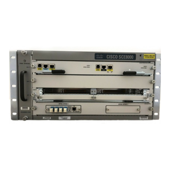
Cisco SCE8000 GBE 설치 - 페이지 20
{카테고리_이름} Cisco SCE8000 GBE에 대한 설치을 온라인으로 검색하거나 PDF를 다운로드하세요. Cisco SCE8000 GBE 21 페이지. 10gbe platform
Cisco SCE8000 GBE에 대해서도 마찬가지입니다: 빠른 시작 매뉴얼 (25 페이지), 구성 매뉴얼 (18 페이지), 제거 및 교체 절차 (36 페이지)

Installing the Power Supplies in the Cisco SCE8000 Chassis
Locate and remove the adhesive label from the system grounding pad on the chassis. (See
Step 4
Figure 4-16
FA N ST
SC E8 00
Place the grounding wire lug against the grounding pad, making sure there is solid metal-to-metal
Step 5
contact.
Secure the grounding lug to the chassis with two M4 screws. Ensure that the grounding lug will not
Step 6
interfere with other hardware or rack equipment.
Prepare the other end of the grounding wire, and connect it to an appropriate grounding point in your
Step 7
site to ensure adequate earth ground for the Cisco SCE8000 chassis.
Installing the Power Supplies in the Cisco SCE8000 Chassis
The Cisco SCE8000 chassis is shipped with the power supplies (AC or DC) already installed. Should it
be necessary to install a power supply module, see the
section on page 9-3.
Cisco SCE8000 10GBE Installation and Configuration Guide
4-20
Installing the System Ground
Grounding
SCE 8000
AT U S
-SC M-E
SC M
1
OPT ICA L
BYP ASS
CON SOL
E
POR T 1
10 100
STA TUS
LINK
1000
OP TIC AL
ACT IVE
BY PAS S
SCE 8000
-SC M-E
2
SC M
OPT ICA L
BYP ASS
CON SOL
E
POR T 1
10 100
STA TUS
LINK
1000
OP TIC AL
ACT IVE
BY PAS S
SCE 8000
-SIP
SIP
3
SPA -1X1
0GE -L-V
2
SPA -1X1
0GE -L-V
2
4
TX
TX
0- FA N
TX
A
RX
TX
C
CT RL
B
RX
D
A
RX
B
C
RX
D
STA TU
OP TIC AL
S
BY PA SS
OP B- SC
1
E8 K- MM
System ground
connector
lug
Wire
SCE 8000
EXTE NDE
D SERV ICE
CON TRO
L MOD ULE
MA STE R
SYS TEM
PO WE R
SCE 8000
EXTE NDE
D SERV ICE
CON TRO
L MOD ULE
MA STE R
SYS TEM
PO WE R
SPA -1X1
0GE -L-V
2
SPA -1X1
0GE -L-V
2
"Removing and Replacing the Power
Chapter 4 Installing the Cisco SCE8000 Chassis
Figure
System ground
connector
4-16.)
Supply"
OL-21054-04
