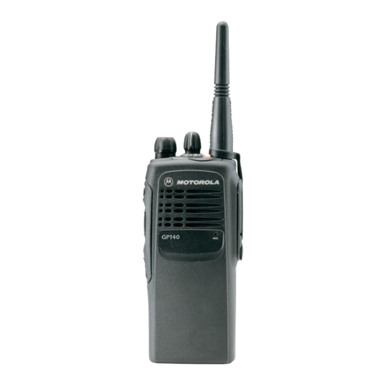
Motorola GP380 Series 서비스 정보 - 페이지 9
{카테고리_이름} Motorola GP380 Series에 대한 서비스 정보을 온라인으로 검색하거나 PDF를 다운로드하세요. Motorola GP380 Series 24 페이지. Professional radio, power distribution and controller
Motorola GP380 Series에 대해서도 마찬가지입니다: 사양 (2 페이지), 서비스 정보 (32 페이지), 서비스 정보 (30 페이지), 서비스 정보 (31 페이지), 서비스 정보 (30 페이지)

1.0
Introduction
This chapter provides a detailed theory of operation for the radio RF circuits. Refer to the relevant
section of this manual for details of the operation of the Controller Circuits.
2.0
Lowband Transmitter
(Refer to Figure 2-1 and the Lowband Transmitter schematic diagram)
The Lowband transmitter consists of the following basic circuits :
I
Power amplifier (PA).
I
Antenna switch/harmonic filter.
I
Antenna matching network.
I
Power Control Integrated Circuit (PCIC).
2.1
Power Amplifier (PA)
The power amplifier (PA) consists of two LDMOS devices:
1.
PA driver IC, U101.
2.
PA final stage, Q100.
The LDMOS driver (U101) provides 2-stage amplification using a supply voltage of 7.3V. The
amplifier is capable of supplying an output power of 0.3W (pins 6 and 7) with an input signal of 2mW
at (pin16). The current drain is typically 120mA while operating in the frequency range of
29.7 - 50 MHz. The power output of this stage is varied by the power control loop which controls the
voltage on pin 1.
SPI Bus
P C I C
V Control
Power Amplifier (PA)
PA Driver
Figure 2-1 Lowband Transmitter Block Diagram.
THEORY OF OPERATION
Antenna switch bias
Gate bias
Antenna Switch/
PA Final
Harmonic Filter
Stage
Chapter 2
Antenna
Matching
Network
