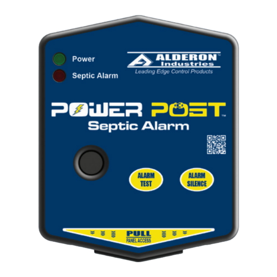
Alderon Industries Power Post VA-02 운영, 유지보수 및 설치 매뉴얼 - 페이지 3
{카테고리_이름} Alderon Industries Power Post VA-02에 대한 운영, 유지보수 및 설치 매뉴얼을 온라인으로 검색하거나 PDF를 다운로드하세요. Alderon Industries Power Post VA-02 4 페이지. 1-zone septic alarm

Power Post™ 1-Zone Alarm Panel - Installation Instructions
Installation of the Alarm Panel
3. If connecting to an existing alarm security system or building automation system (BAS), use 18 gauge 2-conductor wire
to connect the existing product to the AUX inputs on the Power Post™ septic alarm panel terminal block (Fig. 7). See
below for wiring information. The auxiliary contacts on the Power Post™ septic alarm panel are activated when the Power
Post™ system auxiliary contacts or alarm sensor(s) are activated. When connected, run the wire(s) towards the bottom/
center of the alarm panel to go through the wiring access hole once the enclosure cover is replaced (Fig. 8 and Fig. 9).
4. Connect an optional secondary alarm device to the ALM "+" (positive) and "-" (negative) terminals, such as an Alderon™
indoor/outdoor LED strobe beacon (P/N: 7933) which provides remote alarm notification. Use 18 gauge 2-conductor wire,
see below for wiring information. The secondary alarm contacts are only powered and activated when the float inputs on
the terminal block are activated (sensor/signaling device). When connected, run the wire(s) towards the bottom/center of
the alarm panel to go through the wiring access hole once the enclosure cover is replaced (Fig. 8 and Fig. 9).
5. Use 18 gauge 2-conductor wire to connect the Power Post™ system auxiliary contacts or alarm sensor(s) to the FLOAT
inputs on the Power Post™ septic alarm panel terminal block (Fig. 7). See below for wiring information. The Power Post™
septic alarm panel is activated when the Power Post™ system auxiliary contacts or alarm sensor(s) are activated. When
connected, run the wire(s) towards the bottom/center of the alarm panel to go through the wiring access hole once the
enclosure cover is replaced (Fig. 8 and Fig. 9).
Note: When connecting to an Alderon™ Power Post™ pump connection or monitoring system, always refer to its installation
instructions for complete operating information.
CAUTION: Route all wires away from sharp objects and internal components when installing wires.
Auxiliary Alarm Power:
Terminals ALM
("+" and "-")
Connect negative (black) wire to Terminal ALM-
Connect positive (red) wire to Terminal ALM+
(optional secondary alarm device; Alderon™ indoor/outdoor LED strobe beacon)
8-10.2VDC, 150mA maximum
Auxiliary Contacts:
Terminals AUX
Connects to external monitoring device
Normally Open; Single Pole, Single Throw
24VDC, 500mA maximum
Note: The auxiliary dry contacts of the alarm panel are normally open ONLY,
recommended to use 18 gauge 2-conductor wire. Used for remote monitoring.
Power Post™ System Input:
Terminals FLOAT
Zone-1 Alarm
(connects to Power Post™ system)
Normally Open
Note: The auxiliary contacts or alarm sensor(s) from the Power Post™ system
are wired into the FLOAT inputs on the Power Post™ septic alarm panel. The
float inputs of the alarm panel are used with normally open auxiliary contacts
or sensors ONLY, recommended to use 18 gauge 2-conductor wire.
6. After the wiring is completed and before replacing the enclosure cover, run the wire(s) towards the bottom/center of the
alarm panel to go through the wiring access hole once the enclosure cover is replaced (Fig. 8 and Fig. 9).
CAUTION: Route all wires away from sharp objects and internal components when installing wires.
Alderon Industries, LLC - Leading Edge Control Products | 218.483.3034 | [email protected] | [email protected] | alderonind.com
(continued)
(Fig. 8)
(Fig. 7)
#1 = Alderon™ LED strobe beacon
#2 = External Monitoring Device (BAS)
#3 = Power Post™ System
(sensor/signaling device)
(Fig. 9)
Installation Instructions | Page 3
(#1)
(#2)
(#3)
(BAS)
