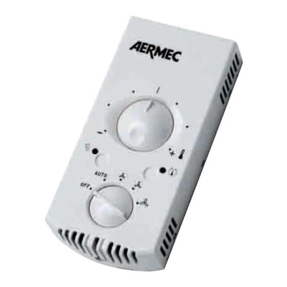
AERMEC PXA I 사용 및 설치 매뉴얼 - 페이지 6
{카테고리_이름} AERMEC PXA I에 대한 사용 및 설치 매뉴얼을 온라인으로 검색하거나 PDF를 다운로드하세요. AERMEC PXA I 7 페이지. Electronic control panel for fan coils

SCHEMI ELETTRICI • WIRING DIAGRAMS • SCHEMAS ELECTRIQUES • SCHALTPLANE • ESQUEMAS ELÉCTRICOS
LEGENDA • READING KEY • LEGENDE • LEGENDE • LEYENDA
CE
= Contatto esterno
External control
Contact extérieur
Externer Kontakt
Contacto externo
IG
= Interruttore magnetotermico
Main switch
Interrupteur général
Hauptschalter
Interruptor magnetotérmico
L
= Linea
Line
Ligne
Phasenleiter
Línea
N
= Neutro
Neutral
Neutre
Neutralleiter
Neutro
MV
= Motore ventilatore
Fan motor
Moteur ventilateur
Lüftermotor
Motor ventilador
PE
= Collegamento di terra
Earthing connection
Branchement à la terre
Erdung
Toma de tierra
C A R A T T E R I S T I C H E
D E I
COLLEGAMENTO
Usare cavi tipo H05V-K oppure N07V-K con
isolamento 300/500 V se incassato in tubo o
canalina.
Per installazioni con cavo in vista usare cavi con
doppio isolamento di tipo H05W-F.
CA R AC T E R I S T I QU E S D E S CA B L E S D E
RACCORDEMENT
Utiliser des câbles du type H05V-K ou N07V-K avec
isolation 300/500 V en cas d'installation dans une
conduite ou une goulotte.
Pour des installations avec câble apparent, utiliser
des câbles à double isolation du type H05W-F.
CONNECTION CABLE SPECIFICATIONS
Use H05V-K or N07V-K type with 300/500 V
insulation if piped or ducted.
In the case of exposed wiring, use H05W-F type
cable with double insulation.
MERKMALE DER ANSCHLUSSKABEL
Bei Verlegung im Rohr oder im Kanal Kabel
vom Typ H05V-K oder N07V-K mit Isolierung
300/500 V verwenden.
Bei Installationen mit offenliegendem Kabel
doppelte Isolierung vom Typ H05W-F verwen-
den.
CARACTERÍSTICAS DE LOS CABLES DE
CONEXIÓN
Utilice cables del tipo H05V-K o bien N07V-K
con aislamiento 300/500 V si van cubiertos en
tubo o en canal de cables.
Para instalaciones con cable a la vista, utilice
cables con doble aislamiento de tipo H05W-F.
Gli schemi elettrici sono soggetti ad aggiornamento; è opportuno fare riferimento allo schema elettrico allegato all' apparecchio.
Wiring diagrams may change for updating. It is therefore necessary to refer always to the wiring diagram inside the units.
Les schémas électriques peuvent être modifies en conséquence des mises à jour. Il faut toujours se référer aux schémas électriques dans les appareils.
Die Schaltschemas können geändert werden; es empfiehlt sich immer auf das mit dem Zubehör verpackte El. Schaltschema zu beziehen.
Los esquemas eléctricos pueden ser actualizados; es conveniente tener en cuenta el esquema eléctrico adjunto al aparato.
22
SC
= Scheda di controllo
Electronic control board
Platine de contrôle
Steuerschaltkreis
Tarjeta de control
SA
= Sonda aria
Room sensor
Sonde ambiante
Raumtemperaturfühler
Sonda ambiente
SW
= Sonda acqua batteria
Water sensor
Sonde eau
Fühler Wassertemperatur
Sonda temperatura del agua
V1
= Velocità minima
Minimun fan speed
Vitesse minimale
Mindestgeschwindigkeit
Velocidad mínima
V2
= Velocità media
Mediun fan speed
Vitesse moyenne
Mittlere Geschwindigkeit
Velocidad media
V3
= Velocità massima
Maximun fan speed
Vitesse maximale
Höchstgeschwindigkeit
Velocidad máxima
C A V I
D I
IG
V2
V3
Y2
CE
SA (EXT)
230 V 50 Hz
L
N
L
N
PE
V1
Y1
MS
SW
EXT
Y1
= Valvola a tre vie
Three way valves
Vanne à trois voies
Dreiwegeventil
Válvula agua de 3 vías
Y2
= Valvola a tre vie • Plasmacluster
Three way valves • Plasmacluster
Vanne à trois voies • Plasmacluster
Dreiwegeventil • Plasmacluster
Válvula agua de 3 vías • Plasmacluster
= Collegamenti a cura dell'installatore
Connections to be made by installeur
Branchements aux bons soins de l'installateur
Bauseitig durchzuführende verdrahtung
Conexiones a efectuar en el lugar
de instalación
= Componenti non forniti
Components not supplied
Composants non fournis
Nicht gelieferte Komponenten
Componentes no suministrados
-
JP1
(SA)
INT
+
