ASL INTERCOM BS 217 User Manual - Page 13
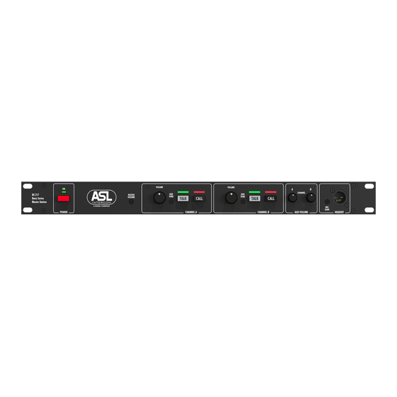
Browse online or download pdf User Manual for Intercom System ASL INTERCOM BS 217. ASL INTERCOM BS 217 15 pages. Dual channel master station
Also for ASL INTERCOM BS 217: Quick Manual (4 pages)
Use high quality cable
Use high quality microphone cable (shielded two conductor cable, minimum 2x 0.30 mm2). In
case multi-pair microphone cable is used, there should be an overall shield and each pair should
consist of two conductors (minimum 2x 0.15 mm2) with separate shield
Use flexible cable
Use flexible single and multi-pair microphone cable instead of cable with solid cores, especially
when the cable is subjected to bending during operation or installation.
Cable screens to XLR pin 1
The screen of each separate microphone cable and/or the screen of each single pair in a multi-
pair cable, should be connected to pin 1 of each XLR-3 connector. Do not connect these screens
to the metal housing of ASL units or XLR-3 wall boxes.
See section 'Earthing Concept'.
Connect metal cable trunks, wall boxes and overall multi-pair cable screens to clean earth
Metal cable trunks, metal wall boxes and overall multi-pair cable screens should be intercon-
nected and, at the 'central earth point' in the intercom network only, be connected to a clean
earth or a safety earth.
See section 'Earthing Concept'.
Keep metal connection boxes and cable trunks or pipes isolated from other metal parts
Metal trunks or pipes for intercom cables and metal connection boxes should be mounted in
such a way that they are isolated from any other metal housing or construction part.
Keep cables parallel as much as possible
When two (multi channel) units in a network are connected by more than one cable, make sure
that these cables are parallel to each other over the whole distance between those units. When
using multi-pair cable, parallelism is ensured in the best possible way.
Avoid closed loops
Always avoid that intercom cables are making a closed loop. So-called 'ring intercom' should not
physically be cabled as a ring..
Keep cables away from electromagnetic sources
Keep intercom cables away from high energy cables, e.g. 115/230/400V mains power or dimmer
controlled feeds for spotlights. Intercom cables should cross high energy cables at an angle of
90º only. Intercom cables should never be in the same trunks as energy cables.
Place power supply in a central position
In case of a system powered by a separate power supply: In order to diminish power losses,
place the power supply as close as possible to where most power consumption occurs, in other
words most user stations are placed.
13