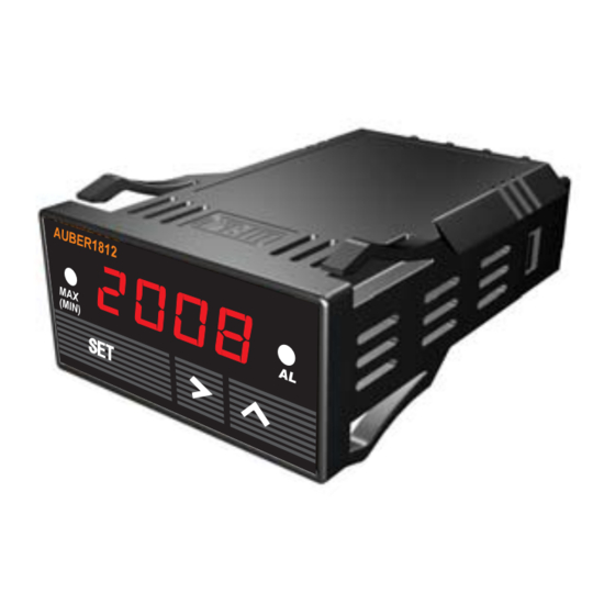
Auber Instruments SYL-1813 Instruction Manual - Page 2
Browse online or download pdf Instruction Manual for Measuring Instruments Auber Instruments SYL-1813. Auber Instruments SYL-1813 2 pages. Multifunction autometer

AUBER INTRUMENTS
b) Alarm Parameter setting is similar to the Basic Parameters setting
in Fig. 3 except access code is 0001 instead of 0089.
Note 5. Relay action setting (SYL-1812 does not contain J2 relay. Its setting
(AH2, AL2) can be ignored).
1) Set AH1=AL1, relay is disabled.
2) Set AH1>AL1, relay is for high limit alarm. See Fig. 1
3) Set AH1<AL1, relay is for low limit alarm. See Fig. 2.
Process Value
A H 1
A L 1
Relay pull-in
Fig 1
Enter Parameter
setting mode
Quick guide,
1) Press
SET
to enter setting mode.
2) Use
and
to input code or parameter. 3) Use
4) Use
to select the next parameter.
5) When no key is pressed for ~ 50 sec, the meter will return to normal mode.
3. Peak Value (Press
SET
a) Peak value description
Symbol
Name
Description
Ma
MA
Maximum
ma-t
MA-t
Time of maximum
mi
MI
Minimum value
Mi-t
MI-t
Time of minimum
End
End
End
Note 6, Peak function is inter locked.
1) When MA is turned off, MA-t can't be set.
2) When MI is turned off, MI-t can't be set.
b) Peak Value setting is similar to the Basic Parameters
setting in Fig. 3 except access code is 0037 instead of 0089.
c) Reset the peak value
The peak values is stored in the memory even the meter is powered
off. To reset them, change display to show MA, MA-t, MI or MI-t. Then,
press and hold " " key for 3 seconds. The display will show "- - - - ",
Λ
indicating the memory (for all four parameters) is reset. The meter will
start to catch the new peak after 2 seconds.
P2/2
Process Value
A L 1
A H1
Relay pull-in
Fig 2
to confirm.
SET
, then input code 0037 to enter)
Range
Initial
/
on off
on
value
/
on off
off
/
on off
off
/
on off
off
D. Terminal assignment
1) 1 and 2 are for power input
2) 4 and 5 are for alarm relay output. See Application example 1
below for how to use it.
3) 3 is for display brightness control. When connecting the
illumination signal (+12 V) to it, the brightness with synchronized with
headlight. If not connected, the brightness can still be controlled by
" " up key.
Λ
4)6, 7, 8 and 9 are for different types of signal input. Use 6 and 7 for
thermocouple input. Use 6,7 and 8 for RTD sensor input. Use 6 and 9
for pressure sensor.
5) 10 outputs regulated 5VDC for powering pressure transducer.
E. Application examples
1) Exhaust Gas Temperature (EGT) measurement
The meter is preset for the EGT application. Wire the meter as
the diagram below. It is ready to run.
2) Set up for Auber 103, 3 Bar MAP Sensor
a) Connecting power to terminal 10, signal to terminal 9, and ground to
Note
terminal 6.
b) Display in bar (0.01bar resolution). Enter the Basic Parameter setting
6
mode with code 0089, i) Select input type, Inty, for 0-5 V input.
c) Display in PSI (00.1psi resolution). Since 1 bar=14.5 psi, the set up
needs to be modified as following. dot=000.0, PuL=000.2, PuH=045.7.
3) Water/oil Temperature Measurement with VDO 150 C/300 F Sender.
a) Connecting VDO sender to terminal 8. Jump a wire between terminal 6
and 7; Jump another wire between terminal 2 and 6.
b) Enter the Basic Parameter setting mode with code 0089, i) Set input
type, Inty, for VDO input. ii) Set CorF to C or F,
Auber Instruments
5755 N Point Parkway, Suite 99
770-569-8420 [email protected]
WWW.AUBERINS.COM
Regulated +5 VDC
°
°
°
Alpharetta, GA, 30022
°
2013.05
