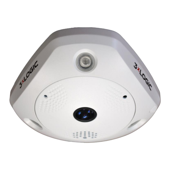
3xLogic VISIX 360 Installation Manual - Page 10
Browse online or download pdf Installation Manual for Security Camera 3xLogic VISIX 360. 3xLogic VISIX 360 16 pages. 3xlogic visix 360 network camera
Also for 3xLogic VISIX 360: Hardware Installation Manual (16 pages)

2 Installation
Before
y ou
s tart:
Make
s ure
t he
d evice
i n
t he
p ackage
i s
i n
g ood
c ondition
a nd
a ll
t he
a ssembly
p arts
a re
i ncluded.
•
Make
s ure
a ll
t he
r elated
e quipment
i s
p ower-‐off
d uring
t he
i nstallation.
•
Check
t he
s pecification
o f
t he
p roducts
f or
t he
i nstallation
e nvironment.
•
Make
s ure
t he
p ower
s upply
i s
m atched
w ith
y our
r equired
v oltage
t o
a void
d amage.
•
If
t he
p roduct
d oes
n ot
f unction
p roperly,
p lease
c ontact
y our
d ealer
o r
t he
n earest
s ervice
c enter.
D o
n ot
•
disassemble
t he
c amera
f or
r epair
o r
m aintenance
b y
y ourself.
Make
s ure
t hat
t he
w all
i s
s trong
e nough
t o
w ithstand
t hree
t imes
t he
w eight
o f
t he
c amera.
•
For
t he
c amera
t hat
s upports
I R,
y ou
a re
r equired
t o
p ay
a ttention
t o
t he
f ollowing
p recautions
t o
p revent
I R
reflection:
Dust
o r
g rease
o n
t he
d ome
c over
w ill
c ause
I R
r eflection.
P lease
d o
n ot
r emove
t he
d ome
c over
f ilm
u ntil
•
the
i nstallation
i s
f inished.
I f
t here
i s
d ust
o r
g rease
o n
t he
d ome
c over,
c lean
t he
d ome
c over
w ith
c lean
soft
c loth
a nd
i sopropyl
a lcohol.
Make
s ure
t hat
t here
i s
n o
r eflective
s urface
t oo
c lose
t o
t he
c amera
l ens.
T he
I R
l ight
f rom
t he
c amera
•
may
r eflect
b ack
i nto
t he
l ens
c ausing
r eflection.
The
f oam
r ing
a round
t he
l ens
m ust
b e
s eated
f lush
a gainst
t he
i nner
s urface
o f
t he
b ubble
t o
i solate
t he
•
lens
f rom
t he
I R
L EDS.
F asten
t he
d ome
c over
t o
c amera
b ody
s o
t hat
t he
f oam
r ing
a nd
t he
d ome
c over
are
a ttached
s eamlessly.
2.1 Ceiling
M ounting
Steps:
1.
Drill
t hree
s crew
h oles
a nd
t he
c able
h ole
a ccording
t o
t he
s upplied
d rill
t emplate.
10225 Westmoor Drive, Suite 300, Westminster, CO 80021 | www.3xlogic.com | (877) 3XLOGIC
Hardware Install Manual |
V ISIX
3 60
N etwork
C amera
1
A
TOP
Drill
T emplate
HoleA:
f or
c ables
r outed
t hrough
t he
c eiling
S crew
h ole
1 :
f or
M ounting
B ase
1
Figure
2 -‐1 Drill
T emplate
1
1
0
