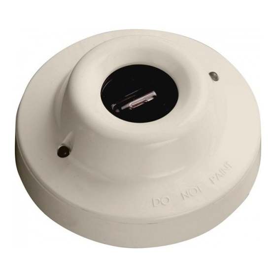
Apollo 65 Series Installation Manual
Browse online or download pdf Installation Manual for Security Sensors Apollo 65 Series. Apollo 65 Series 4 pages. Base mounted marine uv flame detector

www.acornfiresecurity.com
PP2402/2011/Issue 2
8
www.acornfiresecurity.com
Marine Series 65 Base Mounted Marine UV
Flame Detector, Installation Guide
General
The Series 65 (S65) Ultraviolet (UV) Flame Detector, part no 55000-026 MAR, is designed for
use where open fl aming fi res may be expected. It is sensitive to ultraviolet radiation emitted
by fl ames during combustion. Since it requires only UV radiation the S65 Flame Detector
responds also to stationary fl ames with no fl icker such as cigarette lighters and blue gas
fl ames.
Response to fl ames
The Marine UV Flame Detector signals an alarm state by switching an alarm latch on,
increasing the current drawn from the supply from 550μA to a maximum of about 75mA.
This fall in the impedance of the detector is recognised by the control panel as an alarm
signal.
The alarm current also illuminates the detectors integral LED. A remote indicator connected
between the L1 IN terminal and the –R terminal will have a voltage equal to the supply
voltage less 1 volt across it and so will illuminate.
Electrical considerations
To ensure correct operation of the detector the control panel must be arranged to supply a
maximum of 33V DC and a minimum of 12V DC in normal operation. The supply may fall to
6V DC in alarm conditions if a supply current of at least 10mA is available at this voltage.
To ensure effective illumination of the integral LEDs and any remote indicator, the supply to
the detector should exceed 12V. To restore the detector to quiescent condition, it is neces-
sary to extinguish any fl ames in view and interrupt the electrical supply to the detector for a
minimum of one second.
1
