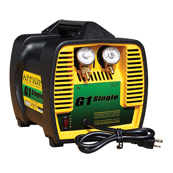
Appion G1 Single Operation Manual - Page 17
Browse online or download pdf Operation Manual for Test Equipment Appion G1 Single. Appion G1 Single 20 pages. Single cylinder

Machine Specifications
PARTS DIAGRAM
Dia. Part No.
Description
1
MF3627
Inlet Manifold Fitting
2
MF3000
Outlet Fitting
3
MF3612
Inlet Filter Cap
4
LB1402
Front Panel Label
5
WR9000
Power Cord - 115v US
5
WR9230
Power Cord - 230v EU
6
EL5120
Power Switch
7
PL7511
Front Panel Only (no label)
8
GA0700
0-700 PSI Gauge (each)
8
GA0761
PSI & Kg/cm
9
MF3530
Gauge Manifold Fitting (each)
10
EL5028
Motor Start Capacitor - 115v
10
EL5034
Motor Start Capacitor - 230v
11
CA1634
Cylinder
12
LB1415
G1Single Side Label
13
PL7600
Case Side Panel
Appion reserves the right to make changes to product and specifications without notice.
Gauge (each)
2
Dia. Part No.
Description
14
SH3532
Rear Heatsink (small)
15
PL7000
Case Handle
16
AY0030C
Fan Gearbox Assembly w/Fan
17
PL7602
Case Back Panel
18
PL7020
Fan Blade
19
AY0030
Fan Gearbox
20
PL7625
Motor Support Bracket (each)
21
LB1417
G1Single Warning Label - 115v
21
LB1422
G1Single Warning Label - 230v
22
EL5000
Motor - 115v
22
EL5230
Motor - 230v
23
EL5030
High Pressure Switch
24
EL5017
Motor Start Relay - 115v
24
EL5027
Motor Start Relay - 230v
25
SH3525
Front Heatsink (large)
17
© 2012 APPION INC. - ALL RIGHTS RESERVED
G1SINGLE OPERATION MANUAL
