Gage Bilt GB54B User Manual - Page 4
Browse online or download pdf User Manual for Tools Gage Bilt GB54B. Gage Bilt GB54B 9 pages. Pneumatic installation tool
Also for Gage Bilt GB54B: Original Instructions Manual (16 pages)
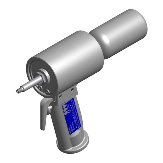
PRINCIPLE OF OPERATION
When the lever assy (1) is depressed, the pressurized air inside the tool is directed to the front side of the piston (3) thus moving it
to the rear of the head cylinder assy (2), forcing the air from the back side of the piston (3) to be exhausted from the standard
exhaust port on side of tool (see page 5). The internal components of the attached nose assembly are simultaneously moving with
the piston (3) to start the fastener installation. When complete, the lever assy (1) is released directing the air to the back side of the
piston (3) reversing the sequence.
3
2
1
Piston in forward position
AIR EXHAUST
Air is exhausted through the standard exhaust port on the side of the tool. To redirect air exhaust to rear of tool, remove set
screw (401816) from rear exhaust hole. If changing exhaust back to side, we recommend applying Vibra-tite® to set screw
(401816) before installation.
STANDARD
EXHAUST
(Side of tool)
OPTIONAL
EXHAUST
(Rear of tool)
GB54B S/N: 1031 AND ABOVE
PLEASE CONTACT GAGE BILT FOR ALL OTHER SERIAL NUMBERS.
3
2
1
Air is exhausted through
Standard Exhaust Port
on side of tool.
Air is exhausted through
Rear Exhaust Port
4
Piston in rear position
Rear Exhaust Port
Plugged
Rear Exhaust Port
Plug removed
Rev. 11/15